Project 767
The goal of Project 767 is to retrieve and analyze data from multiple supersonic flights and learn more about the behavior of the rocket at transonic speeds (Mach 0.8 to 1.2). The major objectives of this project are:
Retrieve data from an onboard recorder
Learn how to use Jolly-Logic-assisted recovery
Get at least three flights worth of data at subsonic speeds
Fly on my first I-motor
Gain experience on I motors and work my way up to higher impulses
Gain data from multiple supersonic (higher than Mach 1) flights
Project 767 is an Academic Independent Study with University School of Nashville in Nashville, Tennessee

Progress Reports
Project 767 Semester 2 Self-Assessment
Throughout the second semester of Project 767, I rapidly gained experience in high-power rocket flight and worked my way up to my first attempt at sending a rocket past Mach 1, 767 mph. Whereas last semester was all about development and learning what it takes to build a Mach 1 rocket, this semester was about testing those designs and putting them into action! In terms of accomplishing my goals for this semester and for the Independent Study as a whole, I did a pretty good job! The goals of Project 767 are to gain data from transonic and supersonic flights, work my way up in classes of rocket motors, and learn how to retrieve data from a rocket. I accomplished this pretty well with multiple flights on larger and larger I motors to subsonic and transonic speeds before attempting my first Mach 1 flight on a J motor. As of right now, I am currently unable to confirm if my first Mach 1 attempt actually achieved its predicted speed, but simulations suggest that it did!
During this semester, I learned a lot more about handling flights on high-power motors and how to recover them safely. I had a couple of flights not land correctly, but they taught me how to make my parachute system more reliable. I also learned that moving up in motors is not particularly as difficult as I thought it would be. I was also able to become much more efficient at building rockets due to the demands of the project coinciding with the demands of things like school, track, and band.
In terms of what I would have done differently, I would have actually moved up in motors sooner and attempted more Mach 1 flights before the end of the semester. With the benefit of hindsight, I now know that the larger I motors are not really harder to use than the small I motors. I would have attempted my L2 certification sooner and moved up to J motors. Granted, at the time, it was much harder to foresee that that would be the case. In the near future, I plan to continue this project outside of school and continue launching past Mach 1 and faster! It would be fun to send a rocket past Mach 1.2 into true supersonic territory!


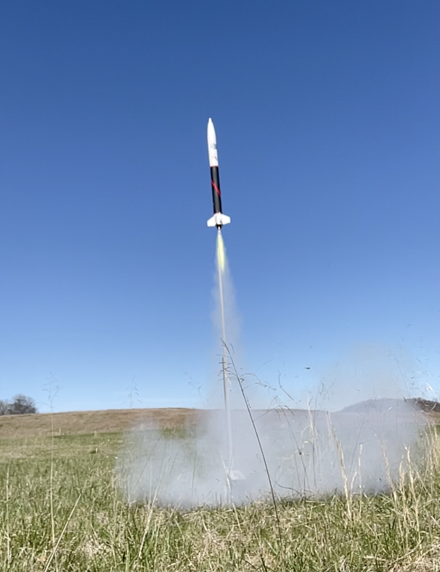
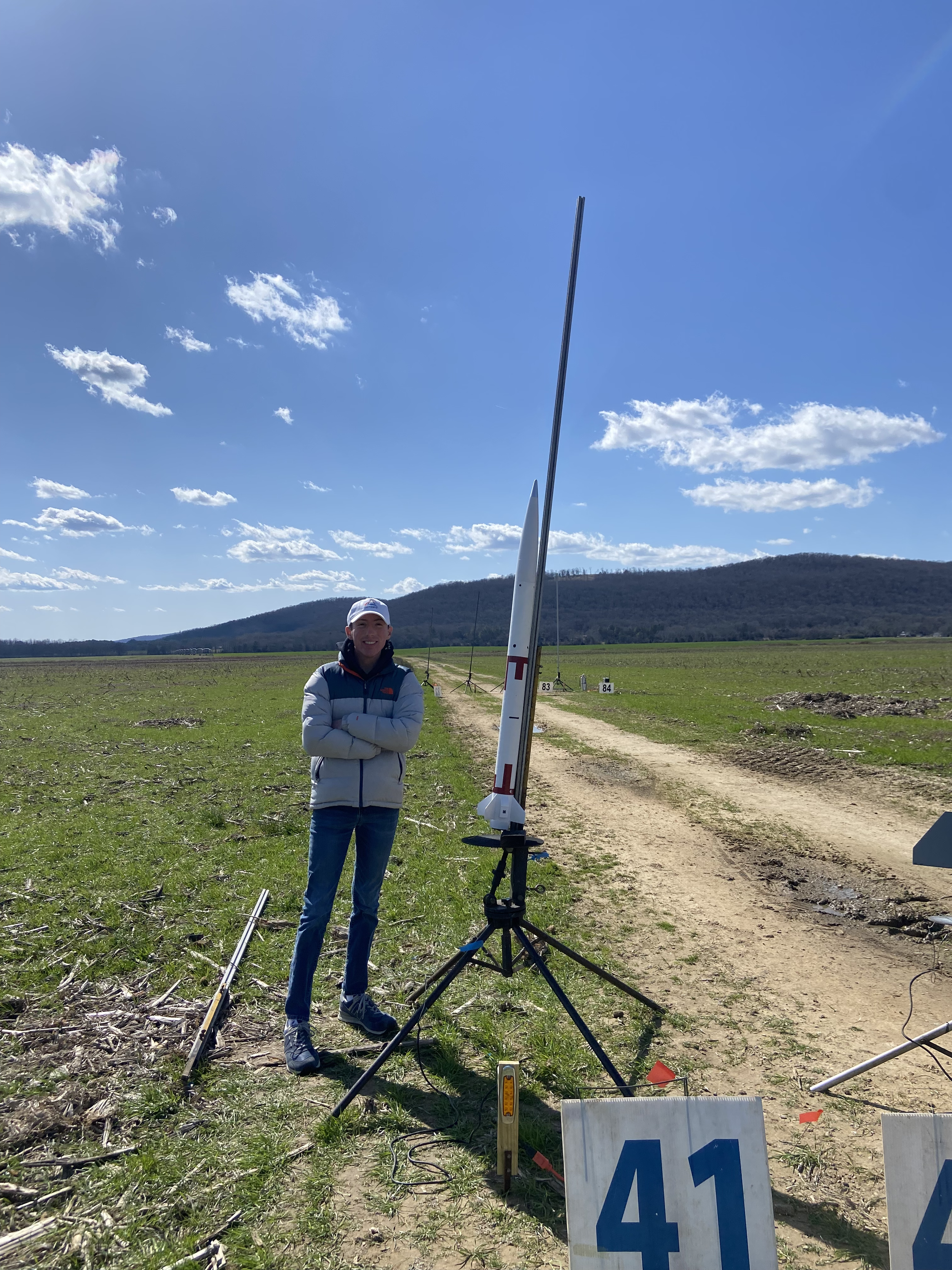
May 12, 2024: Attempting Mach 1
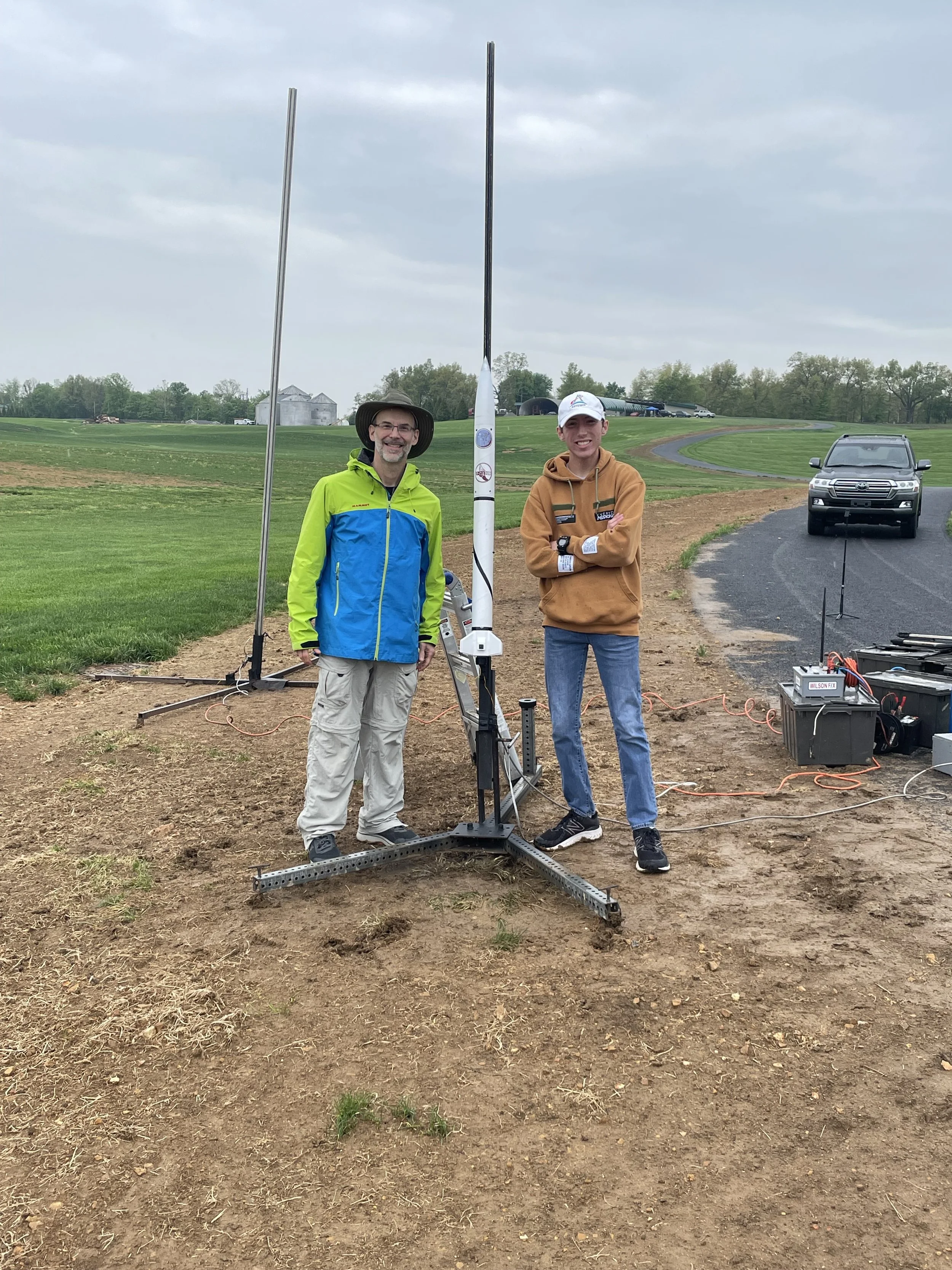
On May 12, I launched Harrier 2A on my first-ever attempt at sending a rocket past Mach 1, 767 mph! This flight also had the secondary objective of earning my Level 2 high power certification, since it was my first flight on a J motor.
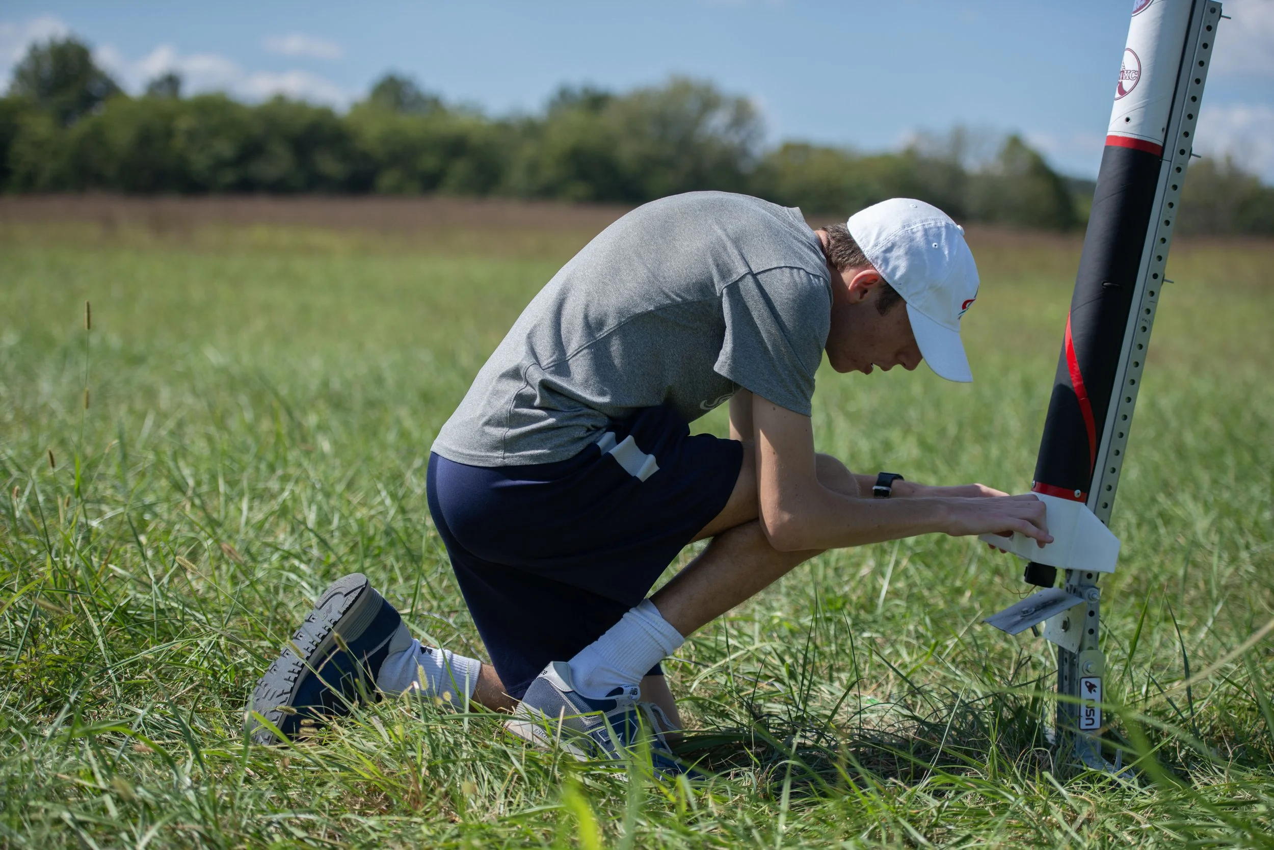
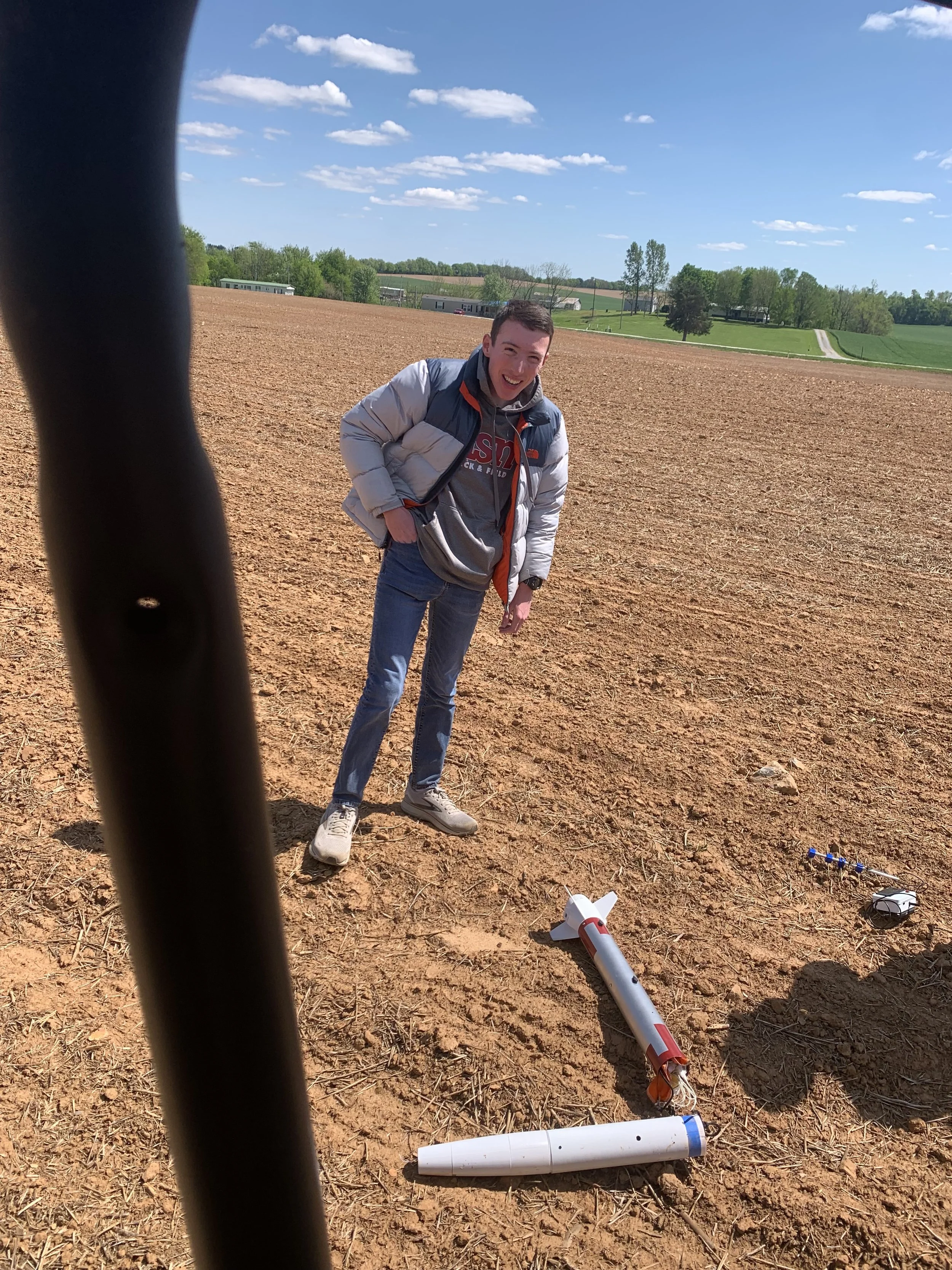
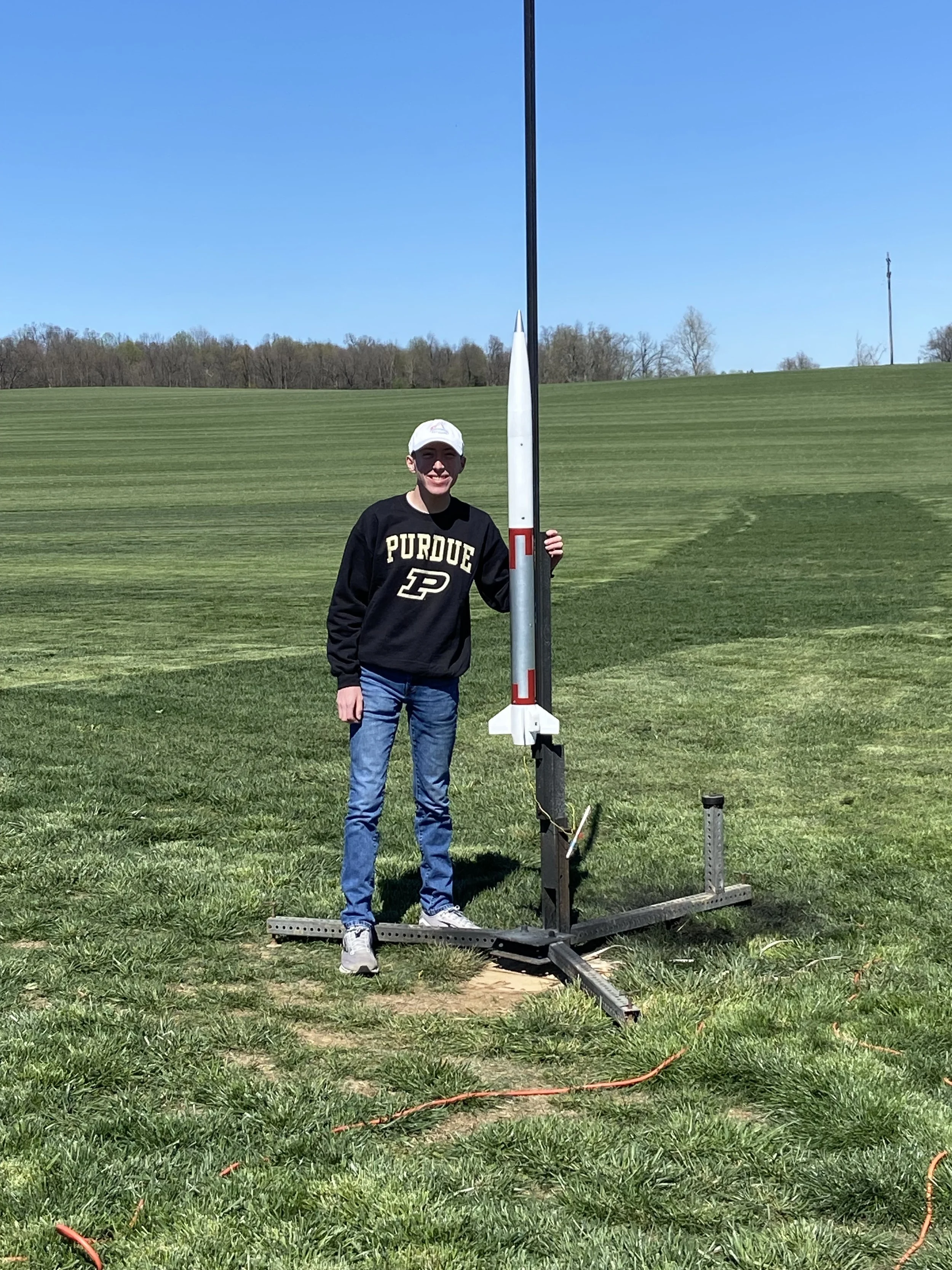
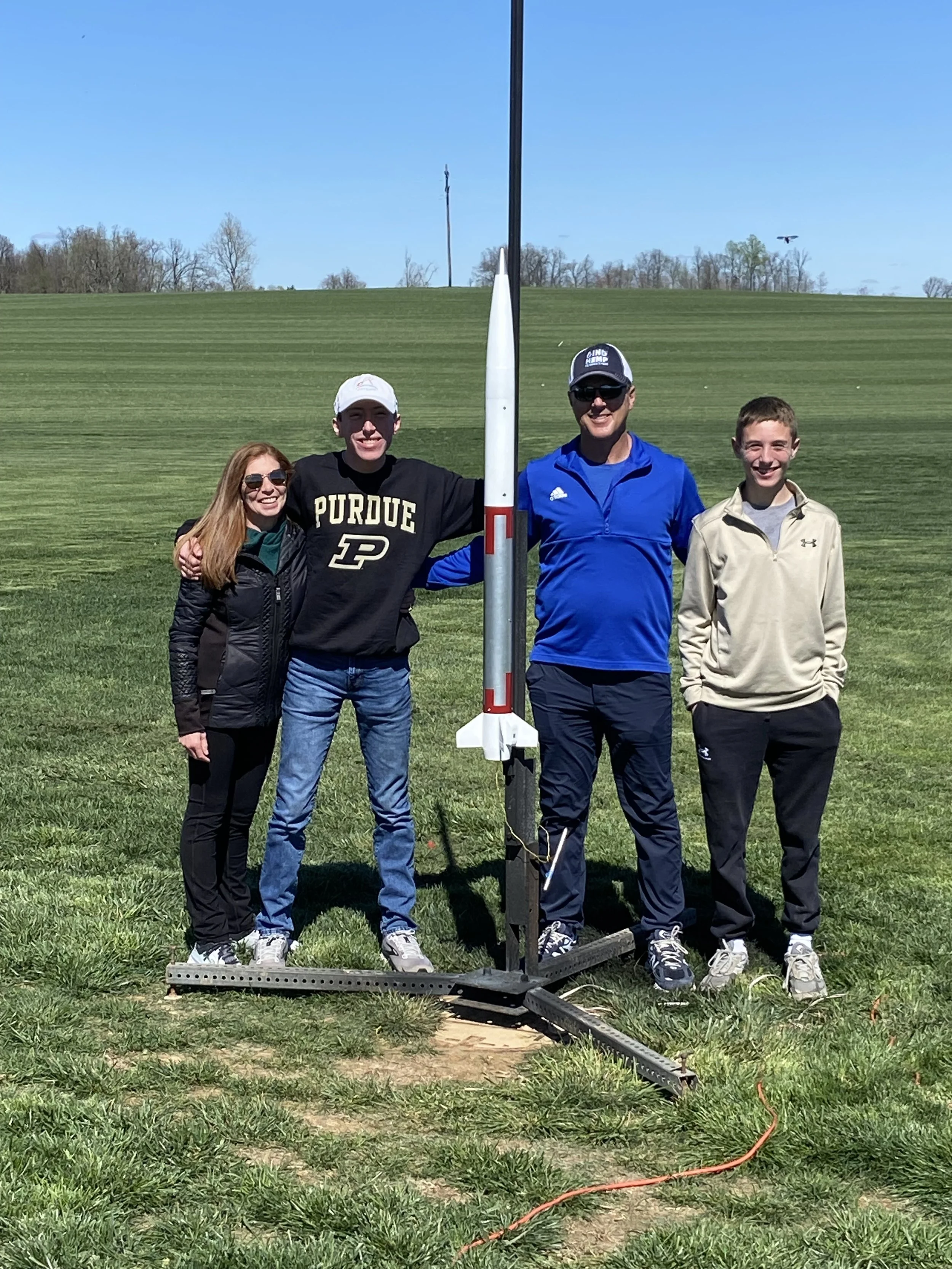
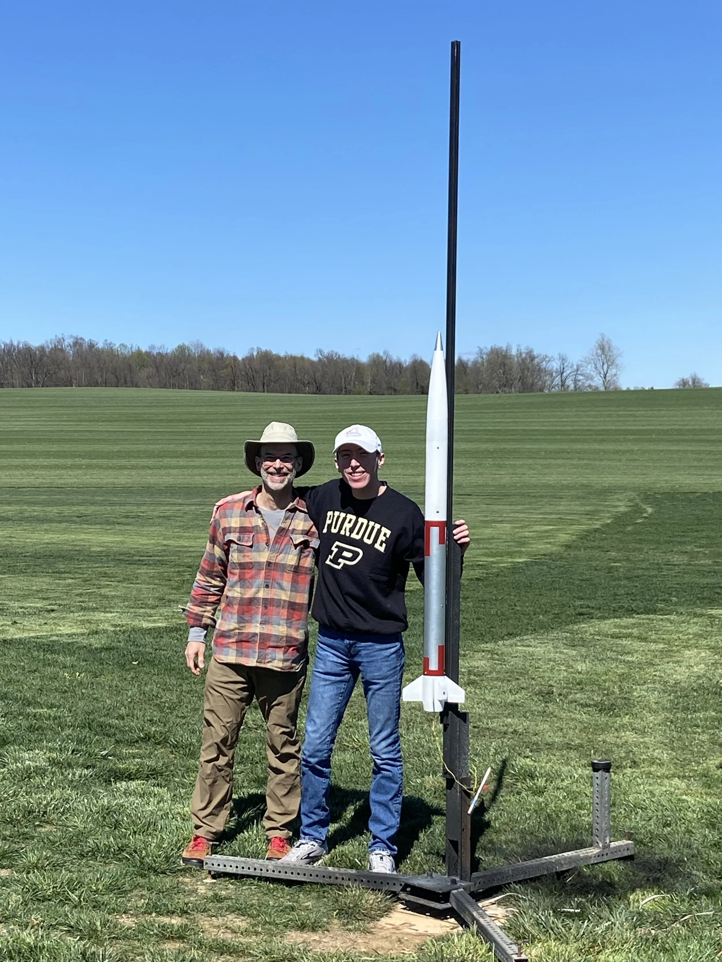
After prelaunch preparations assisted by Will Ostroski, Henry Wykoff, and Jan Brackett, I raised Harrier vertical on the pad in Elizabethtown, Kentucky. Once we were ready to launch, Harrier streaked into the sky powered by its Aerotech J435WS motor. Harrier reached apogee very smoothly despite losing its outward-facing camera due to aerodynamic forces. At apogee, the ejection charge deployed the parachute perfectly, but the payload section broke away from the rocket due to its couple shearing off unexpectedly. While the payload landed mostly intact, this unplanned separation disqualified me from earning my L2 certification from this flight. Meanwhile, the booster had a perfect landing after its parachute was unfurled at 400 ft above the ground by its Jolly Logic Chute Release!
Unfortunately, it appears that the payload experienced some sort of glitch either before launch or during the flight that caused it not to record any data from the flight. Because of this, I am unable to confirm whether or not Harrier exceeded Mach 1 during its ascent even though I am confident that it likely did! Harrier 2A was planned to reach Mach 1.09 on this attempt and overshoot the speed of sound by over 69 mph, leading me to think that it likely did reach Mach 1 on this attempt based on Openrocket simulator data. Even though I was not able to accomplish what I wanted to on this flight, I still had a great time launching and hanging out at the Bluegrass Rocketry launch site!
I am ready to launch the next attempt at Mach 1 as soon as July 20 in Olmstead, Kentucky! Even though the academic school year has come to a close, I'm not done with Project 767 just yet!
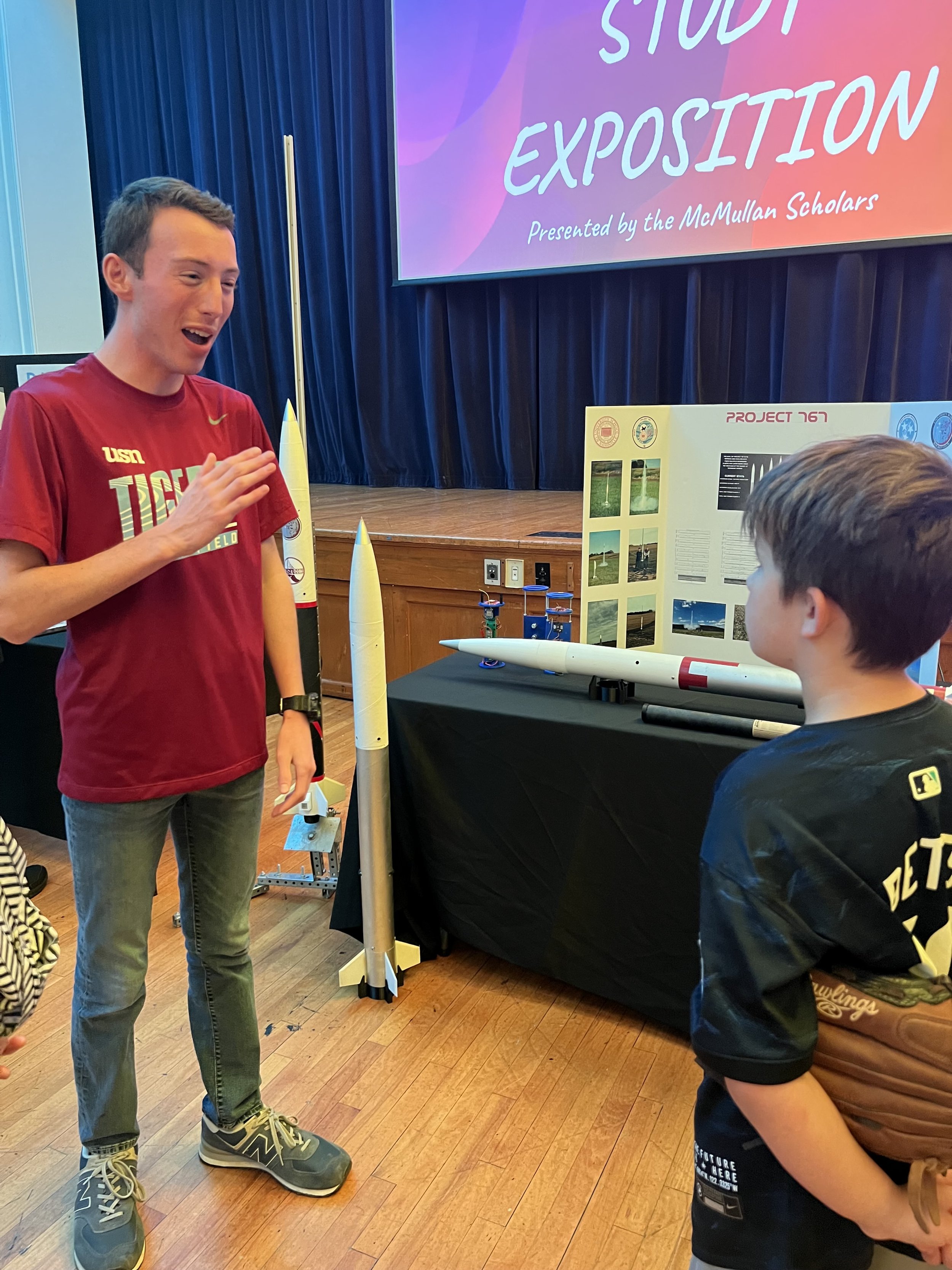
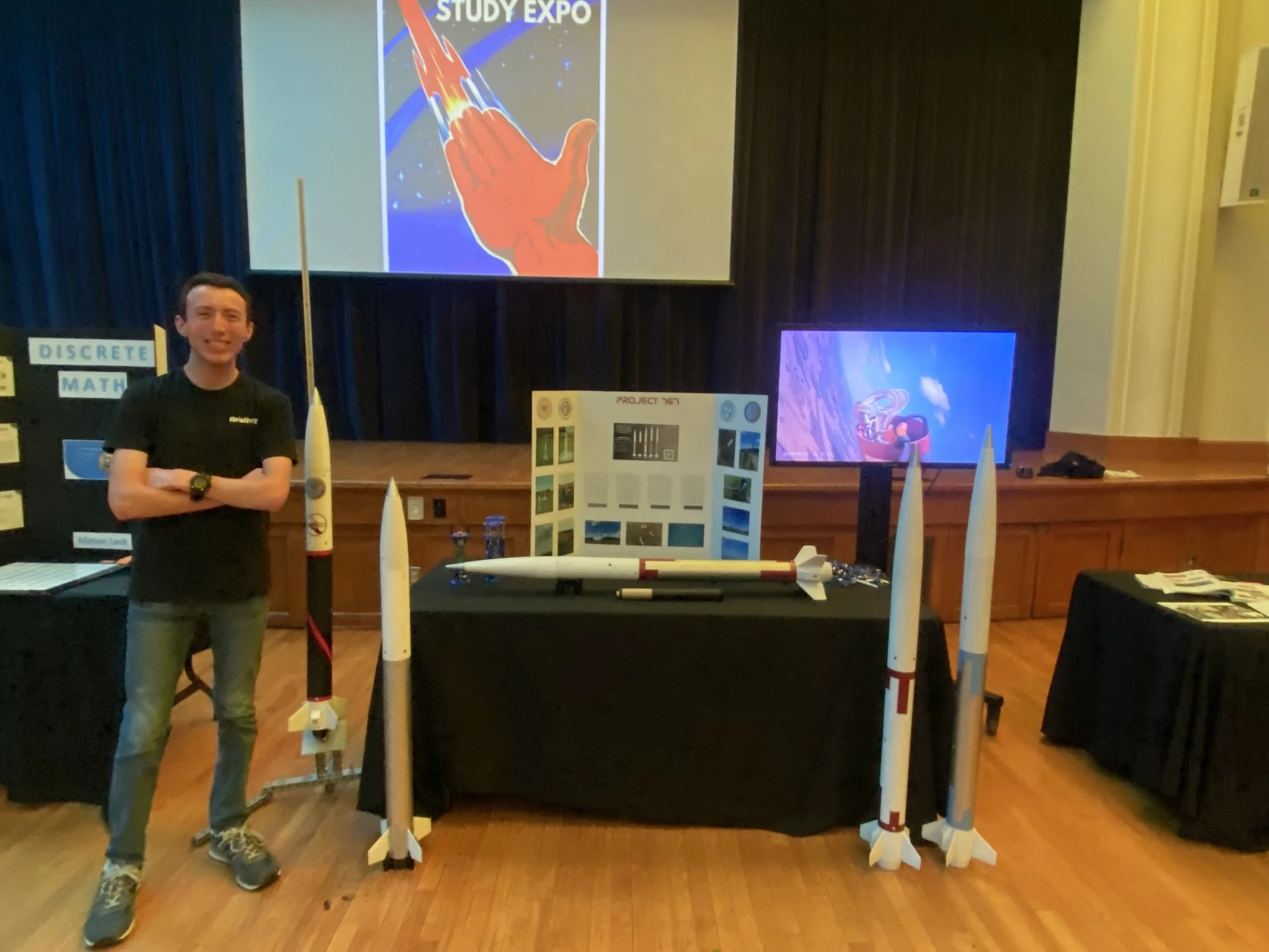
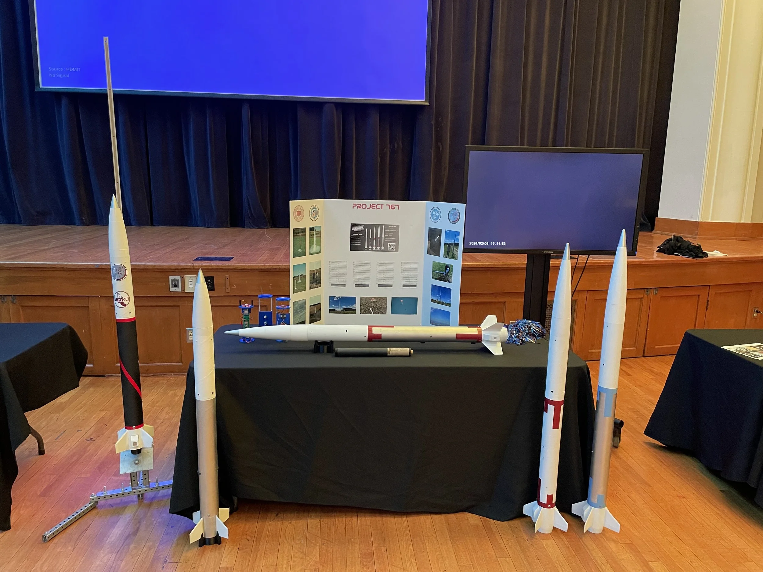
May 9, 2024: Expo Time!
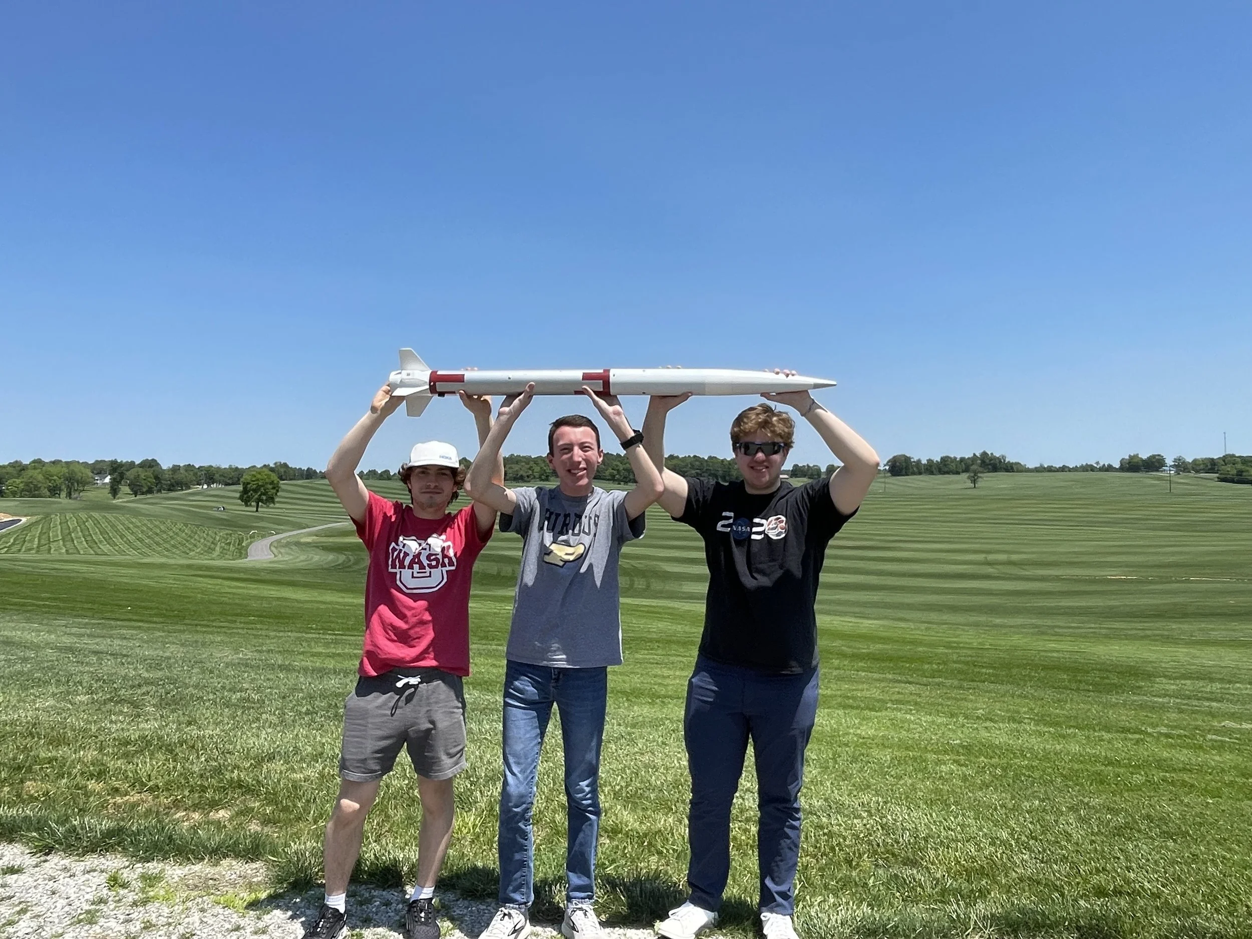
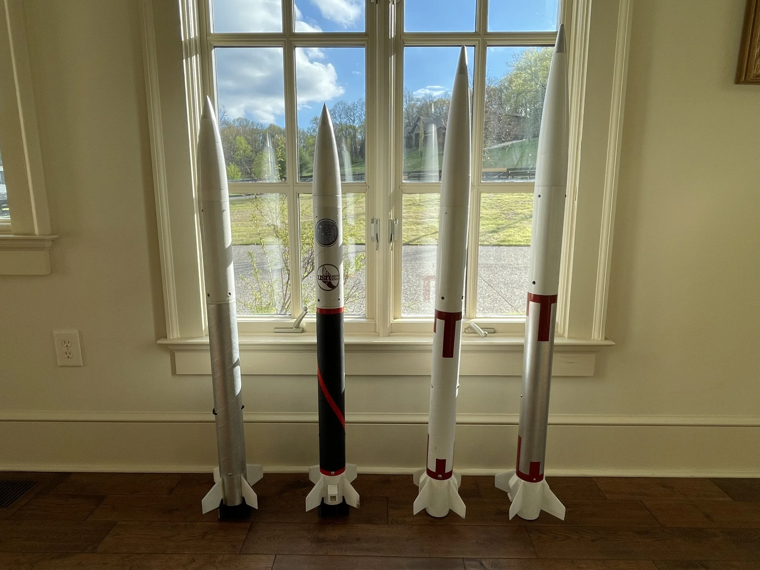
On May 9th, University School of Nashville hosted its first-ever Independent Study Expo! This expo was organized by students so that people working in the school’s amazing independent study program could show the community what we’ve been working on and inspire the next generation of students. Since this was the first time we have done this event, I brought out the Project 767 fleet in full force! My display included Hermes on the mid-power launch pad, Tiger 4, Harrier 1, Harrier 2A, Harrier 2B, the three kinds of payloads used for the project, a spent I500T motor, a trifold with colorful graphs and pictures, and finally, a TV that played videos from the project on a loop.
The event was a massive success and I was overjoyed to be able to explain my project to many friends, younger students, parents, and teachers. I enjoyed answering everyone’s questions and am thankful to USN for putting on the event!
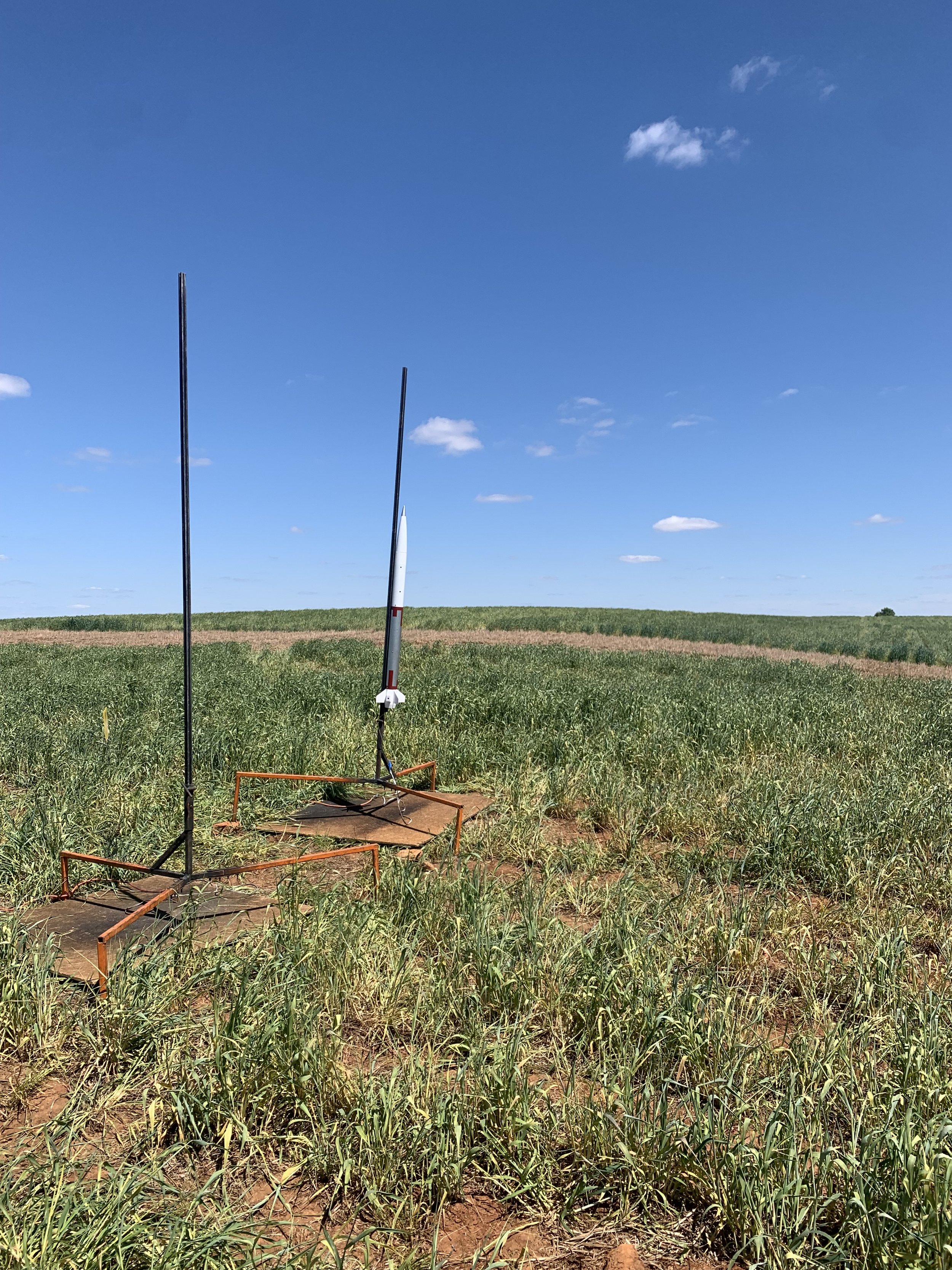


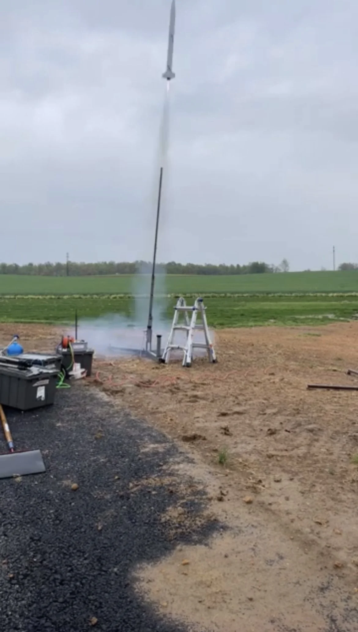
April 21, 2024: A Day Trip to Mach 0.9
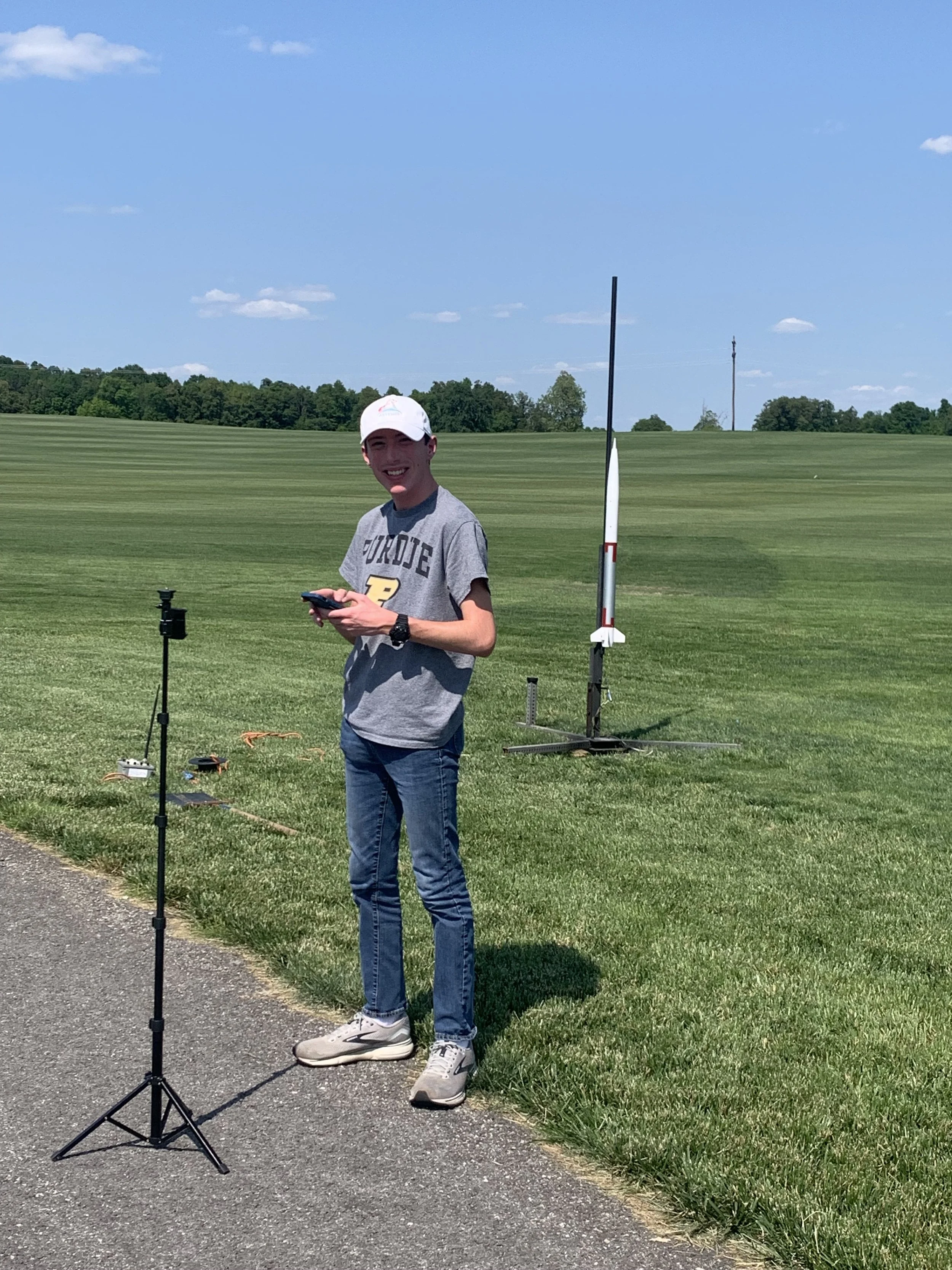
On April 21, I launched Harrier 2A on its second flight! Harrier became the first operational launch from the Music City Missile Club's new launch site in Olmstead, Kentucky. The rocket's I500T motor powered it to a top speed of 317 m/s, which is Mach 0.925! On the way down, Harrier's parachute became stuck inside of its body tube leading to a less-controlled landing than I was hoping for. This also caused one of the fins to be broken during descent because the full 13.5 ft shock cord was not all the way out, leading to the payload section recontacting the booster while the rocket tumbled. The damage from this flight is repairable, however, and I am getting ready to fly again this weekend! The parachute problem can also be solved by mounting it higher on the shock cord so that it comes out immediately.
Weather permitting, I will attempt to launch Harrier 2A next weekend on its first-ever flight past Mach 1! The rocket is currently predicted to exceed Mach 1.1 on a J435WS motor! Since this will be my first flight on a J motor, it will also count as my first attempt at an L2 certification.


April 6, 2024: Sparky Spinning
On Saturday, April 6th, I launched Harrier 2 on its first flight!
While Harrier 2 successfully lifted off the pad, the flight went awry when it began suddenly pitching uncontrollably in different directions. Harrier then reached a maximum altitude of 984 ft (300m) before falling to the ground after the motor's ejection charge failed to deploy the parachute.
After I recovered the rocket, I found with the help of Peter Tarle of Bluegrass Rocketry that the Dark Matter fuel I was using had formed a chunk of metal in the nozzle during the flight that caused it to burn unevenly and point the rocket in the wrong direction. I had never flown with Dark Matter before, so I was unaware of the possibility of it creating metal deposits due to the unburned metal in its exhaust which creates all of the sparks! We found that the likely cause of the ejection charge malfunction was that the gasses exited out of the back of the rocket rather than pressurizing the body tube due to the nozzle being eroded more than usual.
Despite this suboptimal flight, I was able to recover Harrier in a repairable state and am working on getting it ready to fly again in two weeks! This flight also helped prove Steve Ghertner's Version 2 payload. I am working on replacing the nosecone and engine section of the rocket. I am taking the opportunity to upgrade the fins to PETG material, which is less likely to snap under stress than PLA. This will be helpful for high-speed environments where the rocket might experience fin flutter. I am also looking at adding a backup deployment altimeter to the payload that could work as a backup ejection charge in case motor ejection malfunctions again!
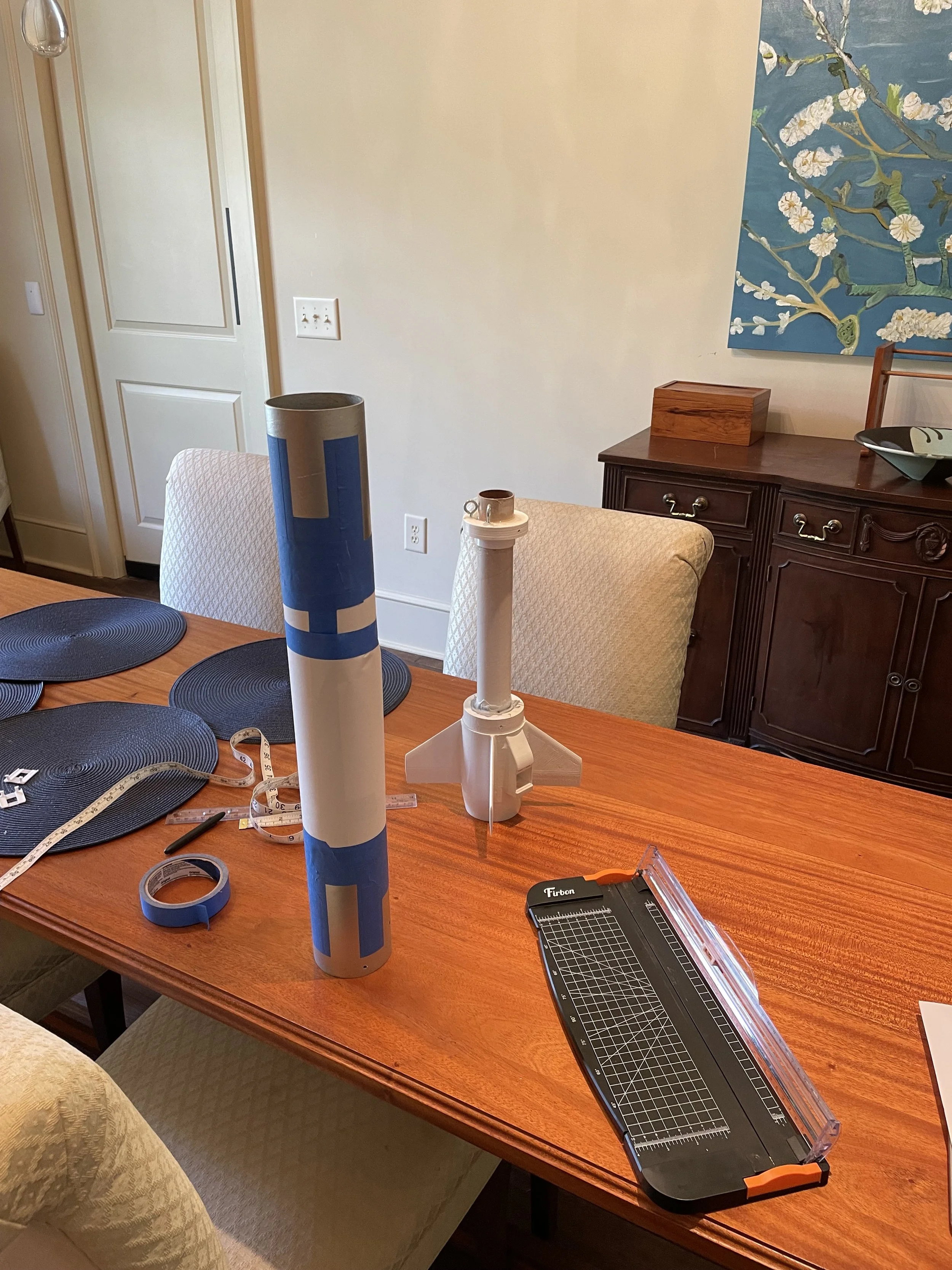
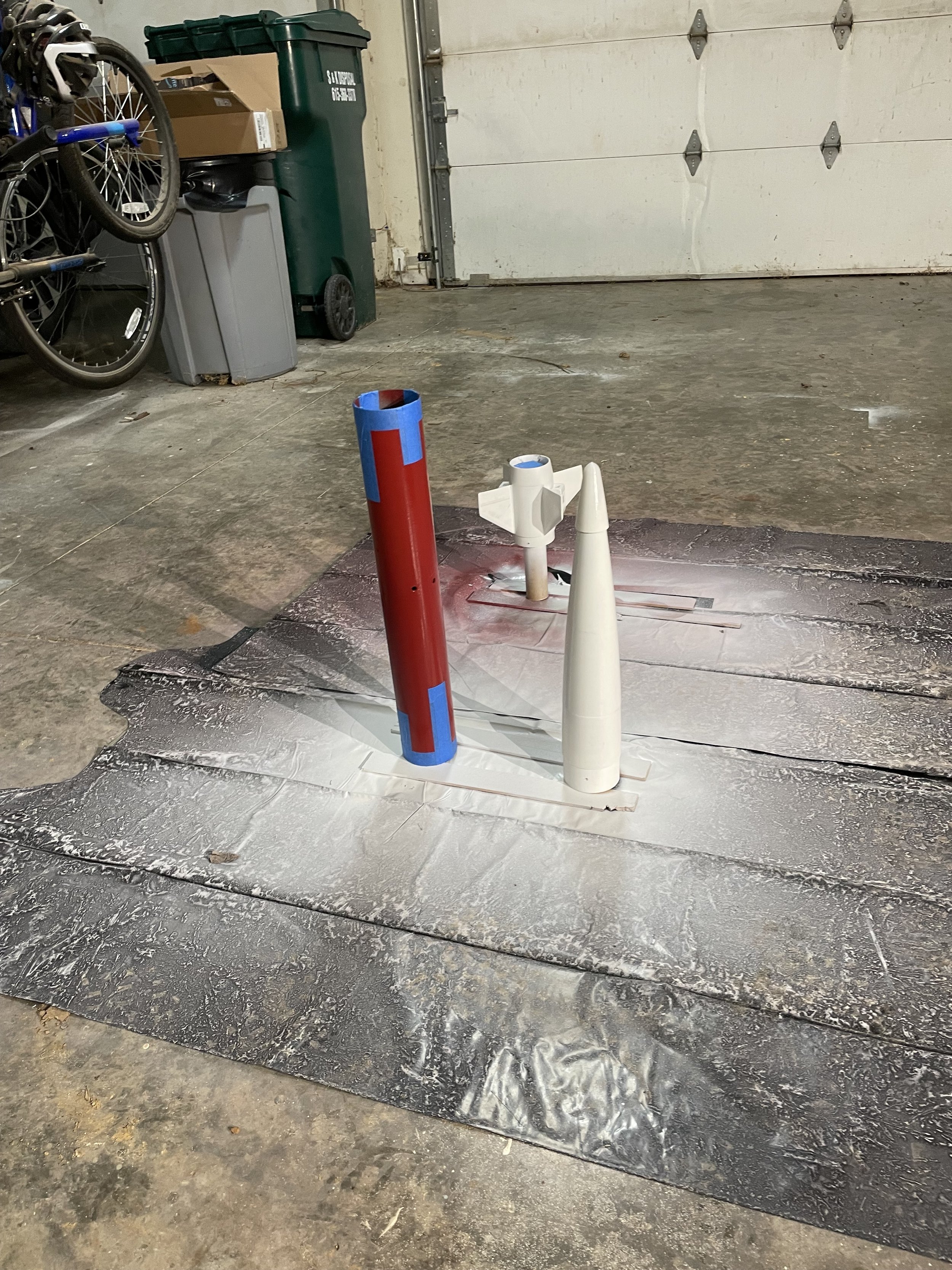
April 5, 2024: Racing Stripes
Today I finished working on Harrier 2 ahead of its launch tomorrow! Over the past couple of days, I have been fixing paint runs on the nosecone and engine mount. Next time, I will do much lighter coats. Today, I worked on masking Harrier’s body tube to paint its Titan-inspired stripes! These follow the same pattern that is on Harrier 1 and are garnet to fit with University School of Nashville’s colors. While it looks complicated, this masking job was actually relatively easily because I used a paper cutter to get straight edges on the painter’s tape. I also covered much of the tube with sheets of paper. Once I was done painting, I de-masked the tube and installed the rest of the screws, shock cord, and other hardware on the rocket! Harrier is ready to fly tomorrow!
March 23, 2024: Painting and Sanding
This week, I have been working on painting Harrier’s body tube, payload bay, and nosecone. I have also done some additional work on the motor mount before painting it. I also drilled all of the holes in the rocket for screws, rivets, launch buttons, and for the altimeter! I was originally planning to launch this weekend, but we had to delay it due to weather. This will give me some extra time to work! The next launch opportunity is April 6th with the Music City Missile Club!


March 20, 2024: Making Progress
Over the past few days, I have made more progress on Harrier 2! I finished assembling the motor mount and applied fillets to the fins. I also attached the boattail and installed the new shock cord mount! This shock cord mount is also the first time I have printed with stronger PETG filament. It took me some time to fix and troubleshoot a printer at school that could print it. I also filled all of the grooves on the tubes with wood putty and sanded them down. Now I can start painting!

March 17, 2024: Building a Harrier
Since I have finished flying Harrier 1 and have tested out my new shock cord system, I have started working on Harrier 2! Today, I started off the project by epoxying the nosecone sections together and cutting the body tube sections down to size. The main visual difference in Harrier 2 compared to Harrier 1 is that the body tube is 51mm longer to accommodate longer I and J motors. It also has a different layout of vent holes and rivets. The interior will also be different in order to accommodate a new shock cord mount that I am working on getting printed!


March 11, 2024: Get Ready for a Little Jolt!
On Monday, March 11, I took advantage of Spring Break and the beautiful Tennessee weather and did some flight testing!
Since the last flight of Harrier 1, one of the components I decided to upgrade was the shock cord mount. The previous design I used involved just looping and tying the shock cord through the walls of the rocket a couple of times. This design was nice because of its simplicity and little weight, but was somewhat flimsy and usually broke after a few flights. It was also just ugly as well.
The new design involves printing a new centering ring to go around the top of the motor tube that has two eye bolts for the shock cord to attach to. Because this is an important new system, I brought Hermes out of retirement to test it out before I put it on a high-power rocket! Hermes launched on a G67G from Chickasaw Trace Park in Columbia, Tennessee, and the new shock cord mount performed perfectly!


March 9, 2024: Coming Out of Retirement
Before I begin building the thrust structure of Harrier 2, I am bringing Hermes out of retirement to flight test a new shock cord mount!
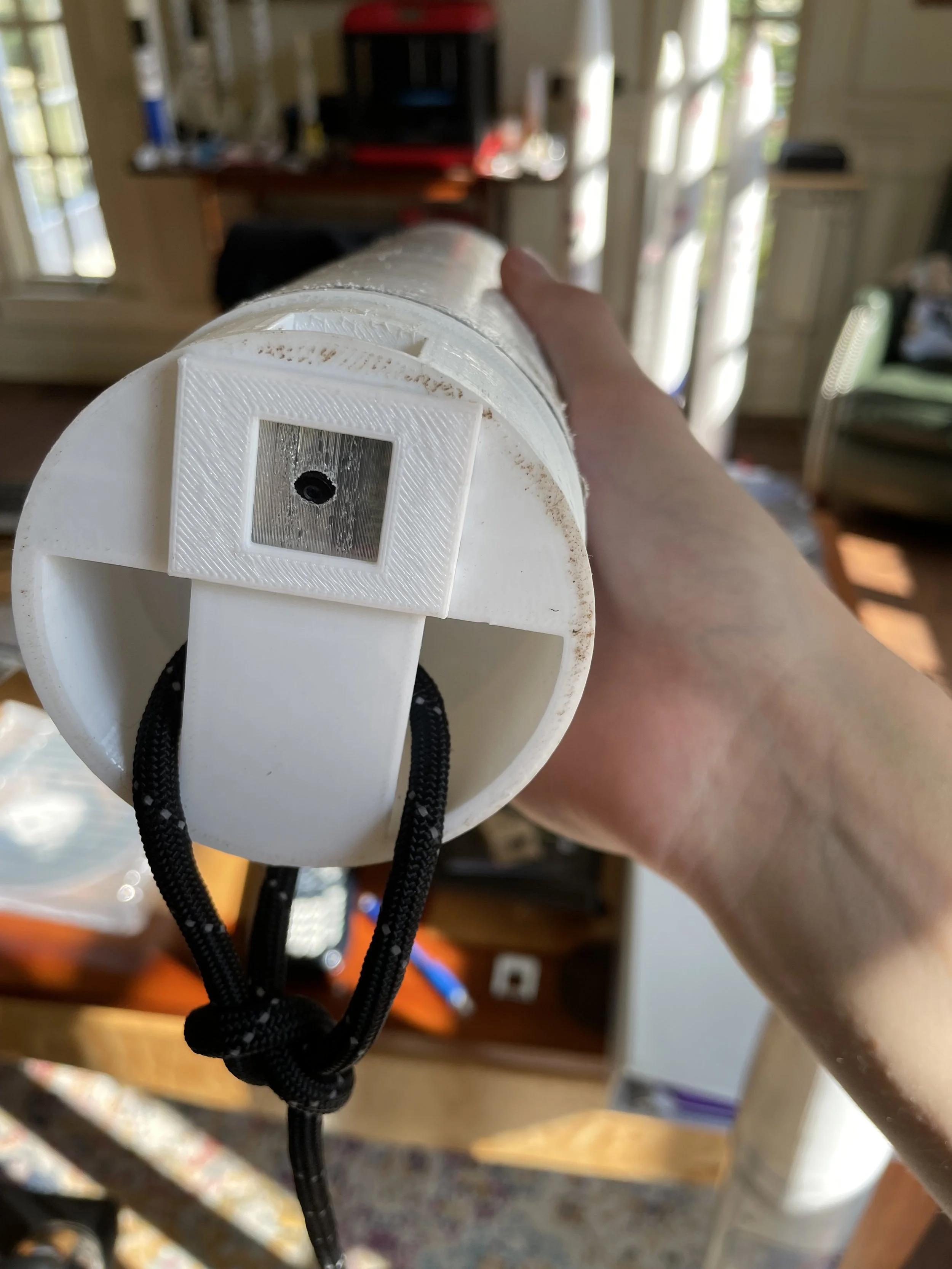
On previous rockets, I mounted the shock cord by looping it through the walls of the body tube. This solution was simple and reliable for a flight or two, but after feeling the jolt of the parachute ejection charge on more than a couple of flights, the walls would start to rip. My new design is made up of a reinforced centering ring that is epoxied to the forward end of the motor tube and is also screwed to the sides of the rocket itself. The ring on this test flight is printed out of PLA, but the one flying on Harrier 2 will be printed out of even stronger PETG. The shock cord is attached by two eye bolts screwed through holes on the top of the ring. As usual, I am tying the cord using bowline knots because of their strength under tension!
I am planning on launching this test flight on the 11th in Columbia!


February 29, 2024: Upgrades, People, Upgrades!
Now that I have completed the goals I set for Harrier 1, namely gaining experience on I motors, learning how to optimize a rocket for flight past Mach 1, and pushing my speed records, I am moving on to building Harrier 2!
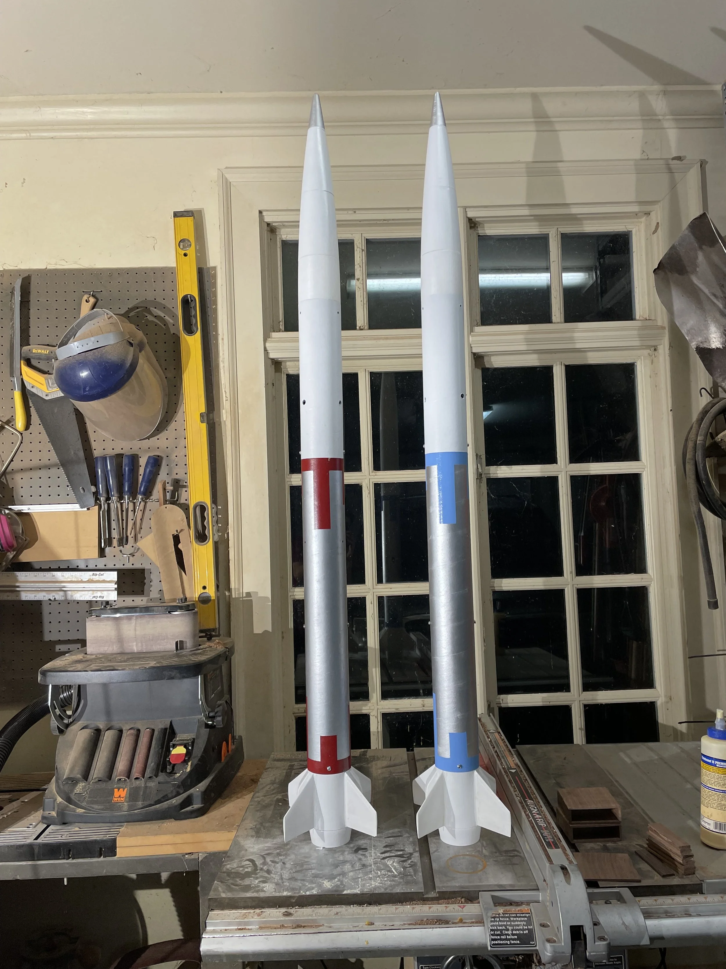
Harrer 2 is mostly the same as Harrier 1 with a few upgrades. The most obvious difference is that Harrier 2’s body tube has been lengthened by 51mm, this is mainly to accommodate longer motors, but also helps with stability! Harrier 2 will also have a new shock cord mount design and will have a longer motor tube. The payload section will be largely the same except that the rivets and altimeter vent holes will now be in groups of three spaced 120º apart rather than groups of four spaced 90º apart. This will help some with aerodynamics and construction. Many of the parts for Harier 2 have already been printed!
As of now, Harrier 2 has at least two scheduled flights. The first flight will be on an I280DM motor and will be my first to exceed a mile in altitude and exceed Mach 0.8! Flight 2 will follow up by exceeding Mach 0.9. Future flights may include actually breaking the sound barrier or getting my Level 2 Certification!


February 24, 2024: Harrier 1 Rises Again!
On Saturday, February 24th, I launched Harrier 1 for the third time! Harrier flew aboard an Aerotech I245G motor to a new personal estimated altitude record of 3953ft! The flight went perfectly and also hit a new estimated personal speed record of Mach 0.6.
This was also my first launch with the Huntsville Area Rocketry Association (HARA). I had a great time and look forward to launching with them in the future! I am hoping to return later in March
The next milestone for Project 767 will be the first flight of Harrier 2! Harrier 2 will use all of the new things I have learned with the successes of Harrier 1 to hit even higher speeds. Flight 1 of Harrier 2 is targeting Mach 0.8 aboard an I280DM motor! This flight also has the possibility of being my first rocket to exceed a mile in altitude. Harrier 2 construction is already well underway with many parts having been printed!


February 4, 2024: Harrier 1 Takes to the Sky!
On Sunday, February 4, Harrier 1 left the the pad for the first time under the power of an Aerotech I140W motor! These flights marked the first high-power launches of Project 767 and were my first using I motors!
The first launch hit a maximum altitude of 854m (2,802ft) and a maximum vertical velocity of 150.8m/s – Mach 0.44!
The second launch reached apogee at 894m (2,933ft) and reached a maximum vertical velocity of 189.9m/s – Mach 0.55! Flight 2 set new personal speed and altitude records!
Both flights carried Steve Ghertner’s instrument unit payload, which recorded acceleration, gyroscope, barometric, and GPS data throughout the entire flight. The GPS was instrumental in recovering Flight 1, because it landed half a mile away.
Flight 2 splashed down in a pond, causing some of the electronics to short out, Harrier 1 is still in good shape though and I look forward to flying it again soon!

January 15, 2024: Waiting for a Launch Date
Harrier 1 is ready to launch but I’m waiting for good weather! In the meantime, I’m working on building drewbrackettrocketry.com and making sure everything is ready to go when the weather clears!
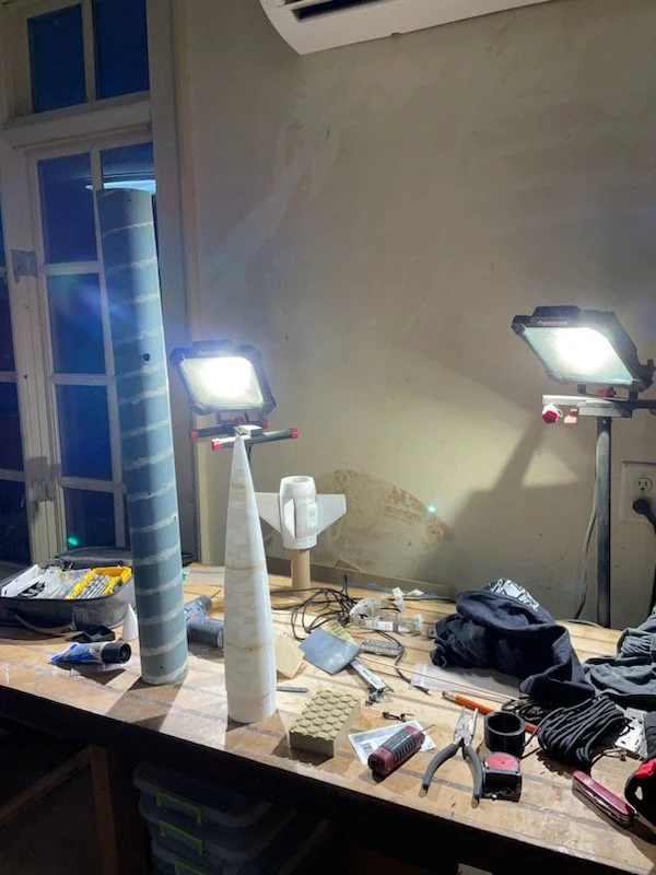
Masking Harrier’s body tube and nosecone during painting


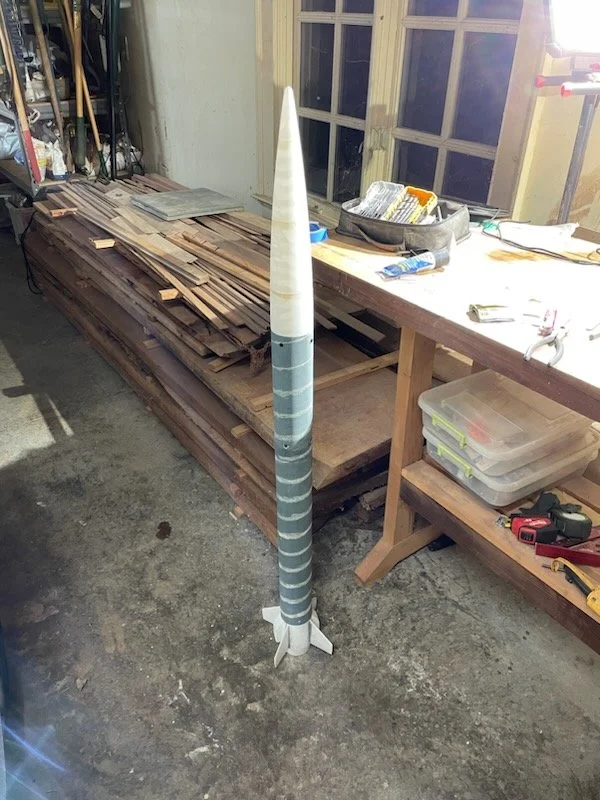
The finished paint job
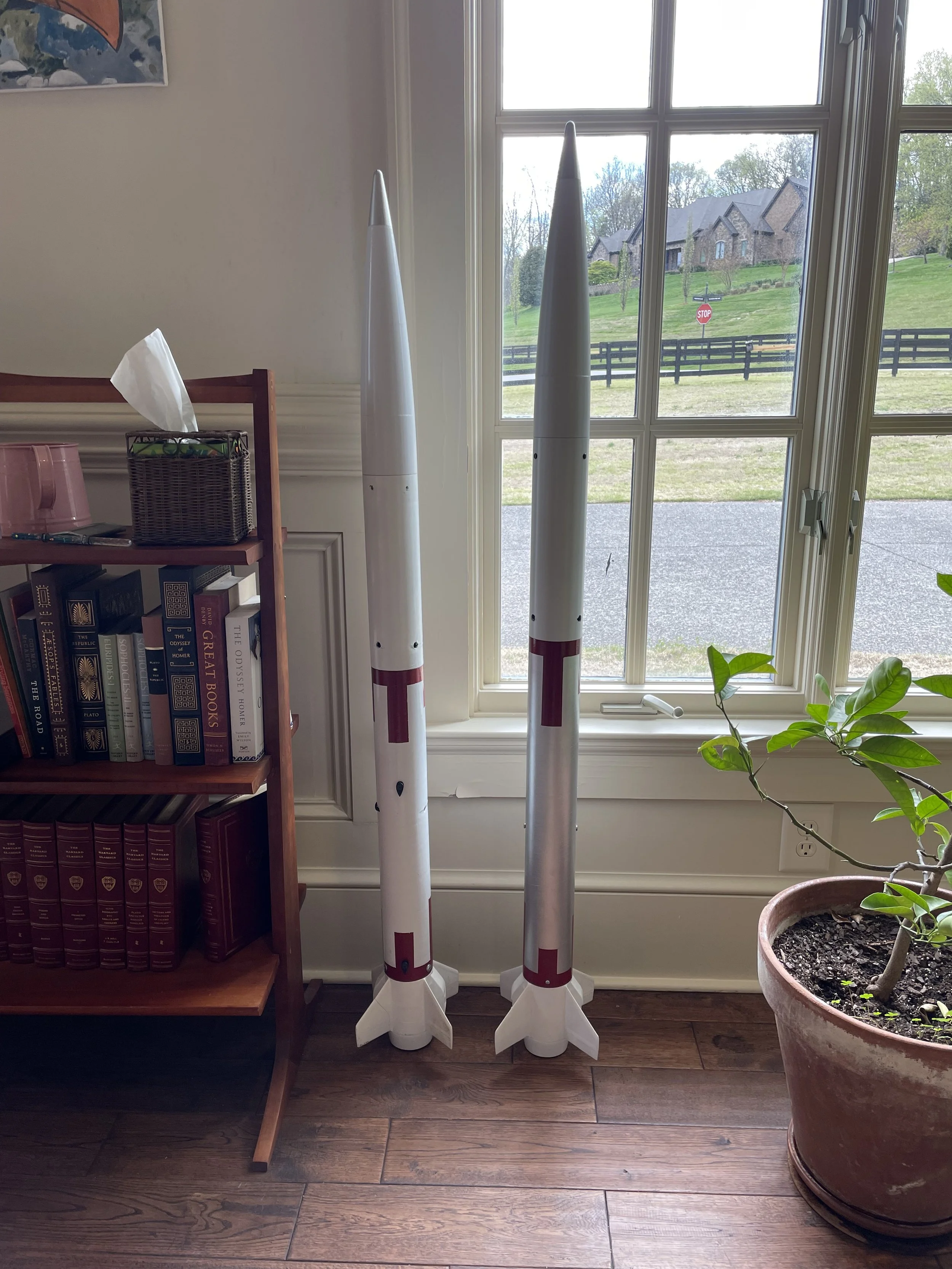
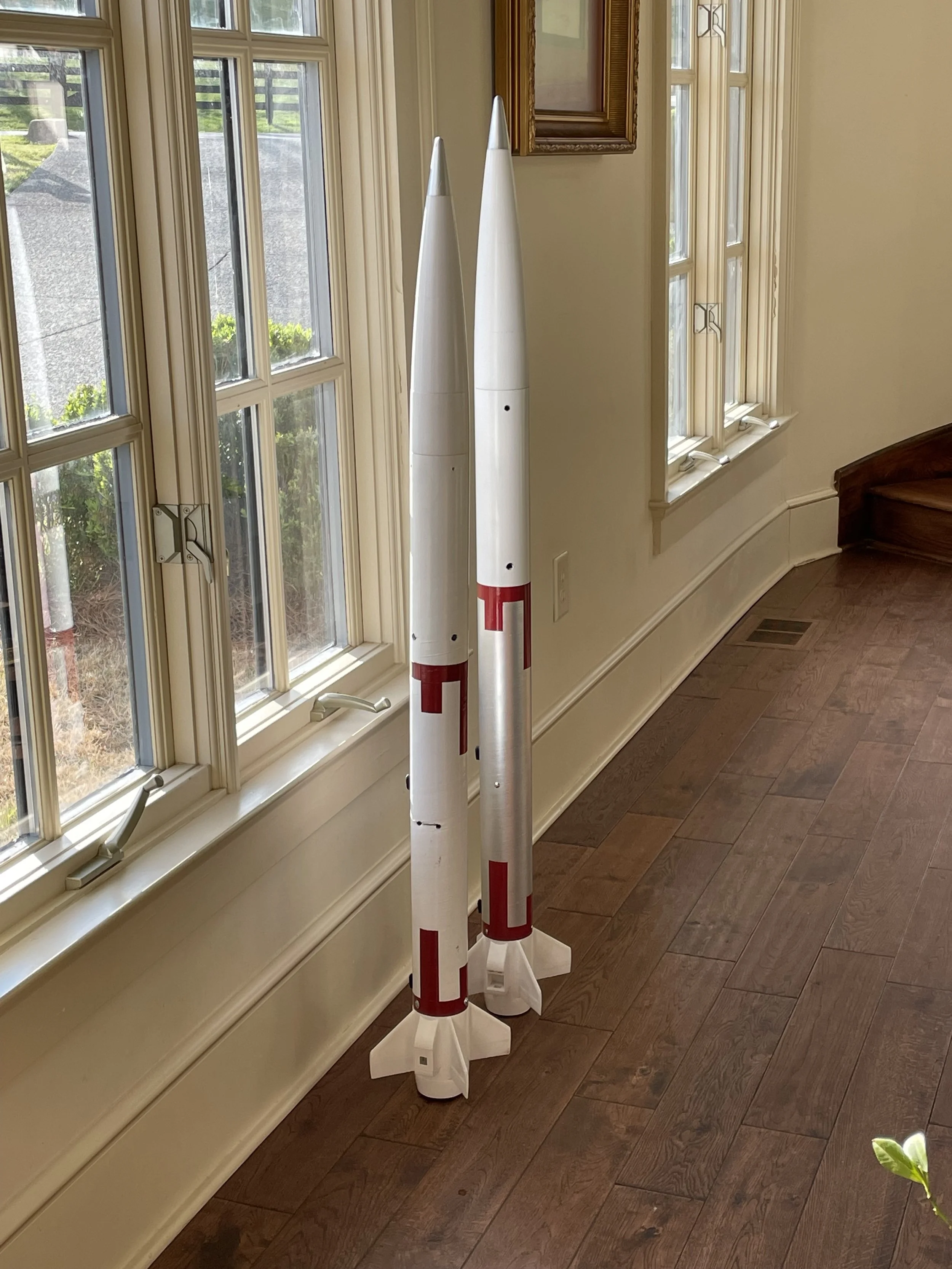
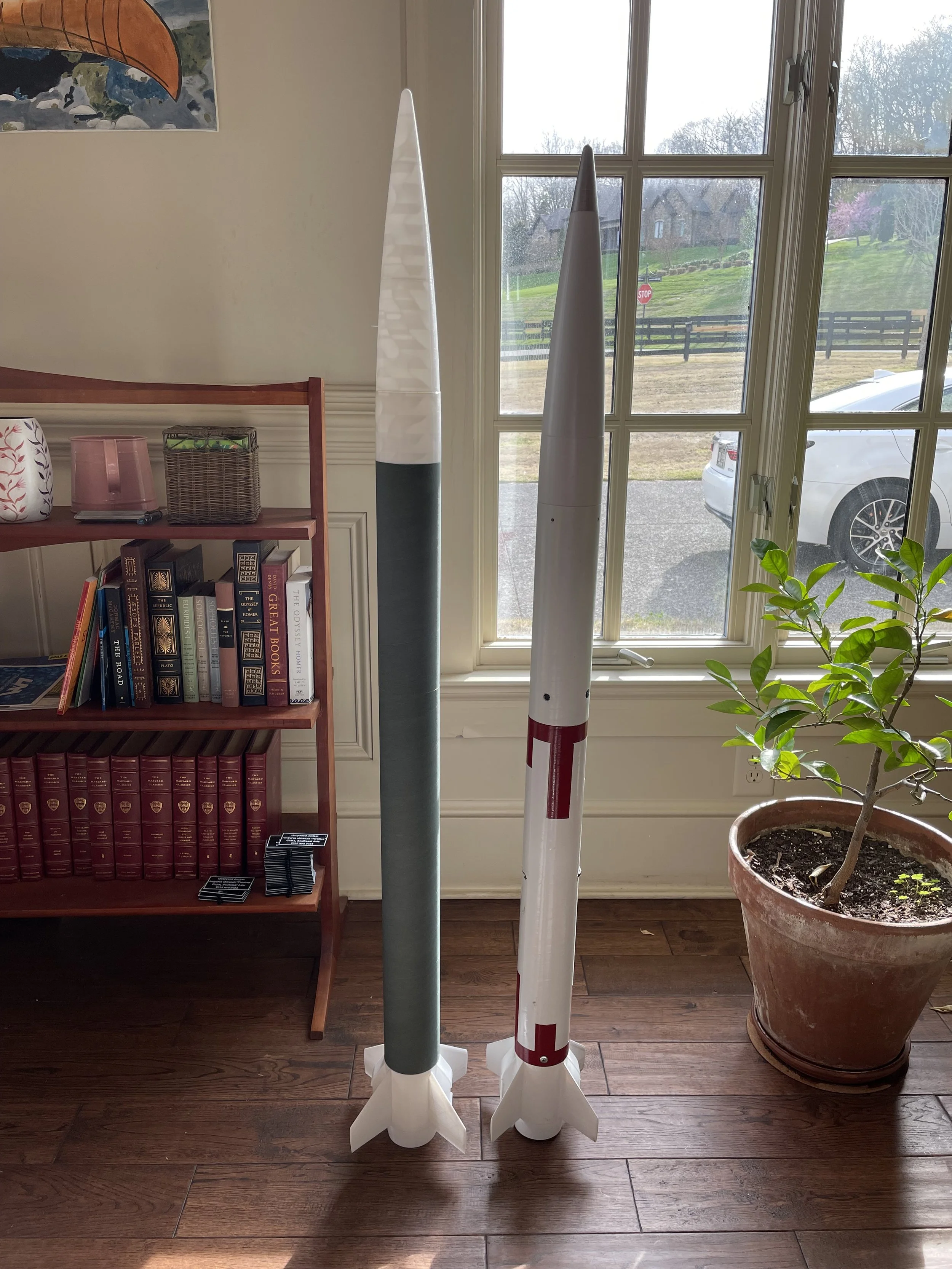
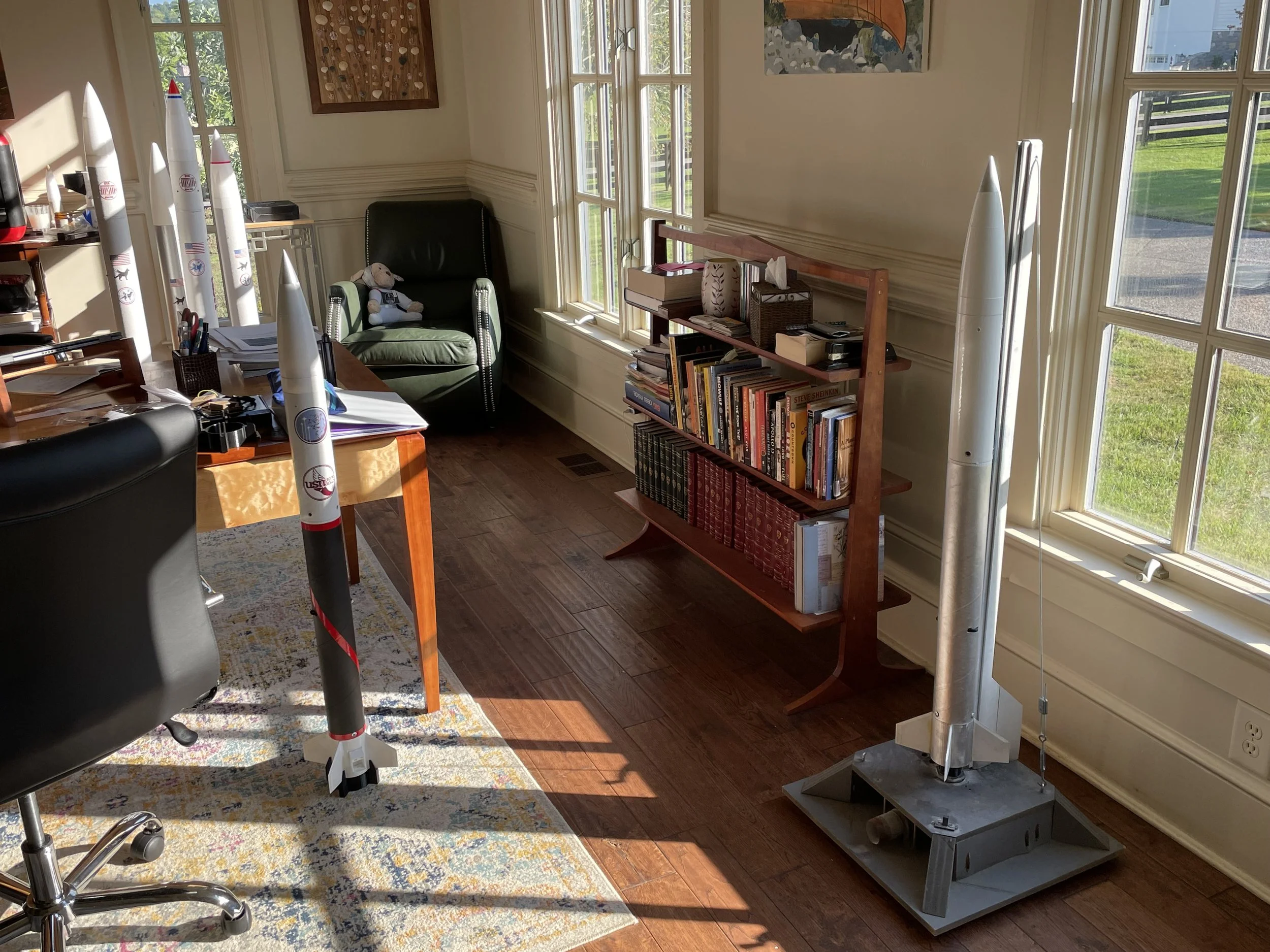
Harrier with Hermes and Tiger 4, as well as Explorator, my L1
December 13, 2023: A Shiny Coat
After a couple of days of painting, Harrier has a fresh coat of paint! The paint job is white with stripes in University School of Nashville garnet. The stripes vary in length, which is inspired by the solid rocket boosters on the Titan IIIC rocket! I also painted the tip of the nosecone to look like metal because it looks cool!
The paint job came out much smoother this time because I filled in all of the gaps with wood putty beforehand!
Harrier’s tubes and nosecone sanded

The full rocket before painting
Harrier’s main section and payload bay
December 11, 2023: Lots of Sanding
Over the past week, I have been working on getting Harrier ready to fly! A big part of this has been drilling holes for different parts like screws, rivets, and launch buttons to fit into. I have also epoxied on the boattail since I finished installing the motor tube and drilled holes in the payload bay for the air pressure to change for altimeter readings. A new challenge I have been working on with this rocket is smoothing out the entire surface. This involved filling the seams that run around the body tubes with wood putty, and then sanding them down until they were smooth. I also sanded the nosecone and motor mount to remove at least some of the bumps that come from 3D-printing parts in layers. With all of this work, Harrier is now ready to paint!
Diagram of Fin Fillets from Nakka Rocketry


The motor mount and fins before fillets
The taped-up motor mount drying
December 4, 2023: Roc-Fil-A
Today I have been working on one of the most subtle, but most difficult and perhaps most important details on Harrier: its fin fillets. Rocket fin Fillets help keep the aerodynamic joint between the fins and the walls of the rocket smooth by getting rid of sharp corners. They also add extra structural stability to the base joints of the fins by adding an extra layer of epoxy. For mine, I used clear Loctite epoxy and applied painters’ tape about an eighth of an inch away from the base of the fin and from the wall of the rocket to get clean transitions. I mixed the epoxy directly onto the fillet area and smoothed it out with a popsicle stick to get a good shape. I had to be extremely careful not to make a mess during this process and sanded the whole engine section afterward.

A render of Harrier 1’s engine section
November 26, 2023: The Near Future
Here is a quick plan for the coming weeks:
I will continue working on Harrier 1. I am currently targeting two launches on Saturday, December 9th with Huntsville’s rocket club aboard expendable I140W motors. These flights will be attempting to fly to Mach 0.6!
I will hopefully start working on a website for easier access to my progress on this project as well as more photos and information.
I am somewhat changing the trajectory of Project 767. Rather than taking a slower approach with a complicated rocket flying one or two supersonic flights at the end of next semester, I will try to get supersonic sooner. I will be looking into possibly getting my Level 2 High Power certification so that I can fly less complicated, but more powerful rockets to get more reps in the supersonic flight regimes. I will likely have some damaged rockets on these initial attempts, but it will help me learn even more!


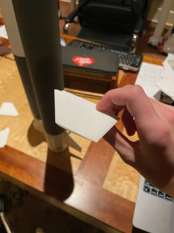
The new fins in Fusion 360 and real life!

Harrier’s airframe (left) is coming together!
Four fins and camera mounts on Harrier’s Motor Mount.
November 25, 2023: Fluid Fin Design
Today, I worked on designing the final major component of Harrier’s airframe, its fins! The fin design kept a few factors in mind. First, I wanted to limit drag as much as possible, meaning the fins needed to be as small as possible but still large enough to have a good stability margin. I found that another way to keep them even more aerodynamic was to give them an airfoil shape, similar to the wing of an airliner. OpenRocket claimed that this would increase the maximum altitude by over 400 feet! I kept my usual number of four fins because it would allow me to keep them smaller and easier to print and attach! I also swept the fins further back than usual, leading to the trailing edge being perpendicular to the bottom of the engine mount. This allowed me to further decrease their size since the rocket’s center of pressure had been moved further back. I ended up with the rocket having a stability margin of 1.47 cal with a payload.
For a quick explanation, model rocket stability is measured by how many rocket diameters or “calibers” the center of pressure, where all of the aerodynamic forces are acting through the rocket, is behind the center of mass of the rocket, where it could be balanced on a finger. The optimal stability margin is between 1.00 cal and 2.00 cal in flight configuration. If the stability margin is below 1.00, the rocket will try to flip around to correct for it, similar to what happens if you throw a dart backward. If the stability margin is above 2.00 cal, the rocket may be unsafe to fly in higher winds, as it will more readily veer into the wind.

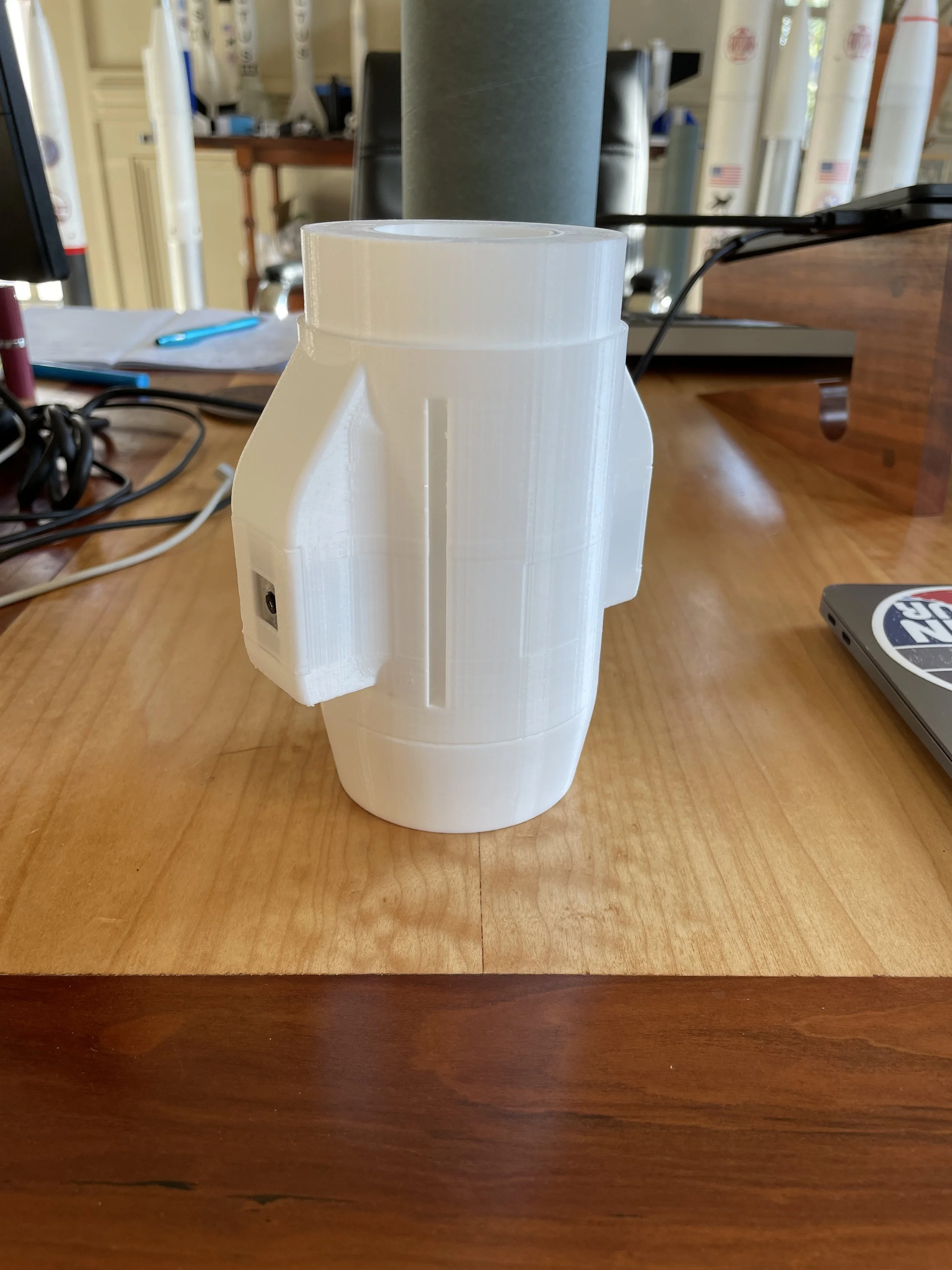
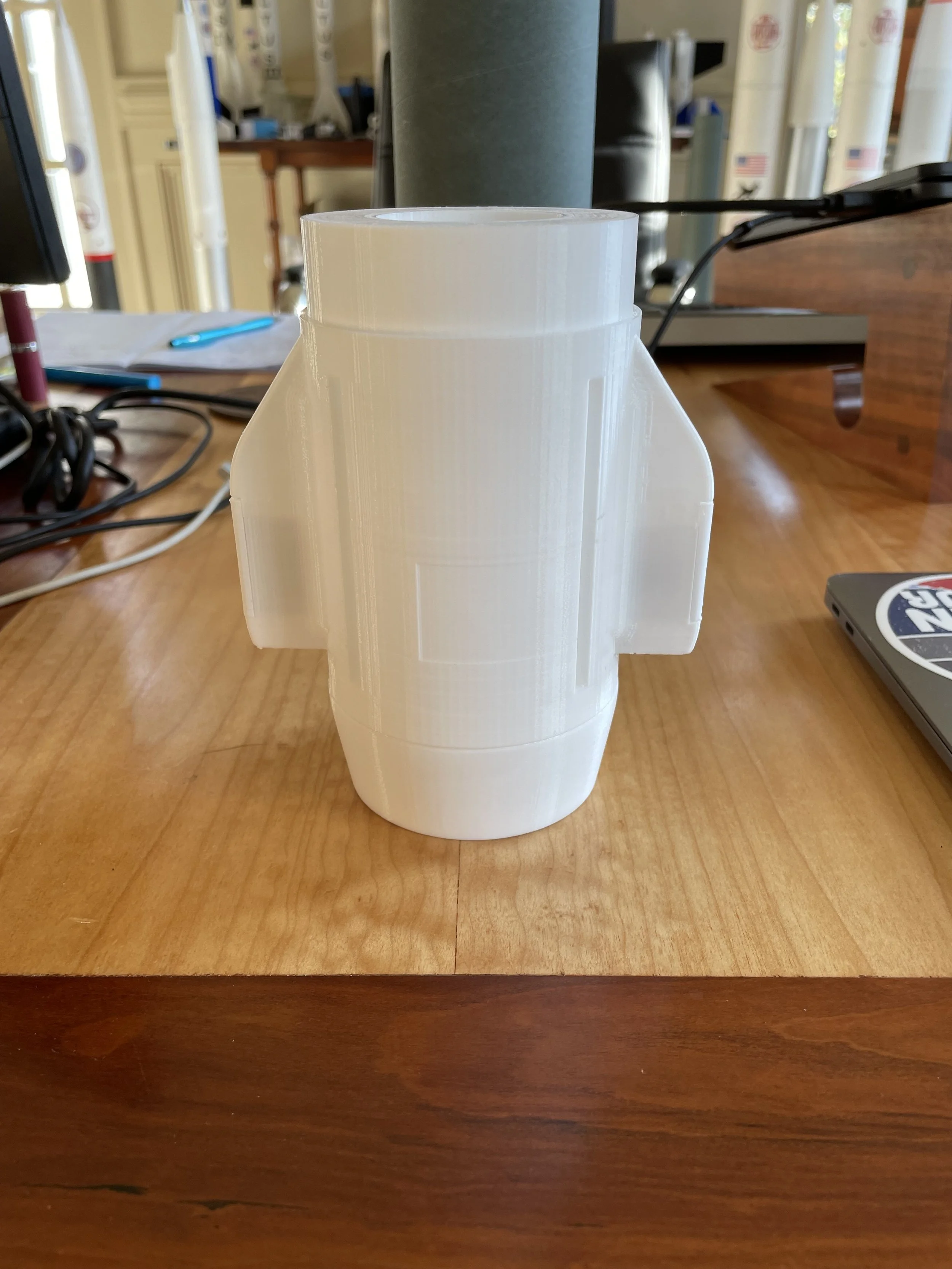
Multiple views of the printed motor mount with its camera covers
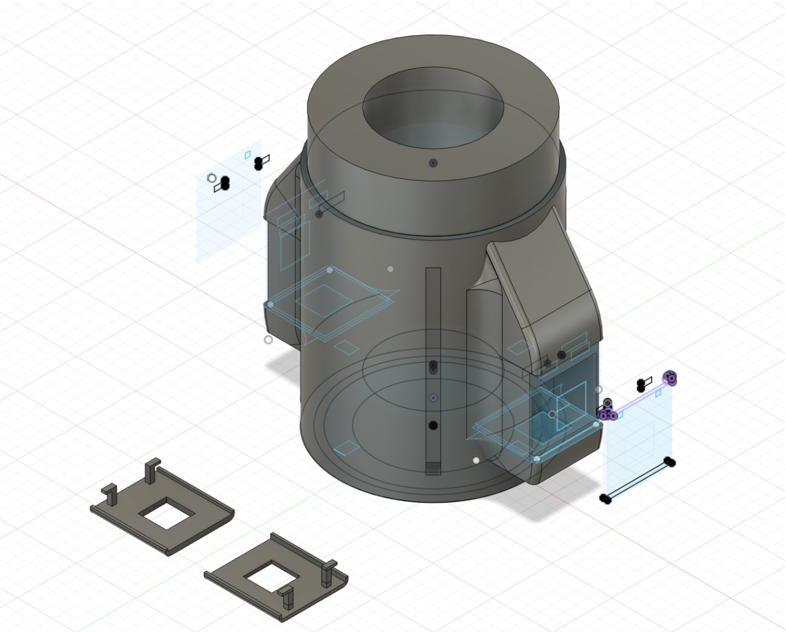
Two views of the motor mount and camera hoods in Fusion! One has the part sketches visible.
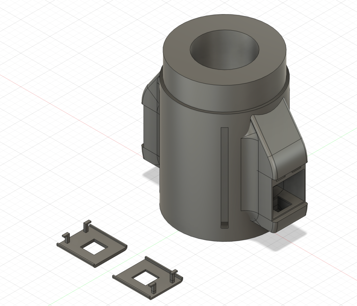
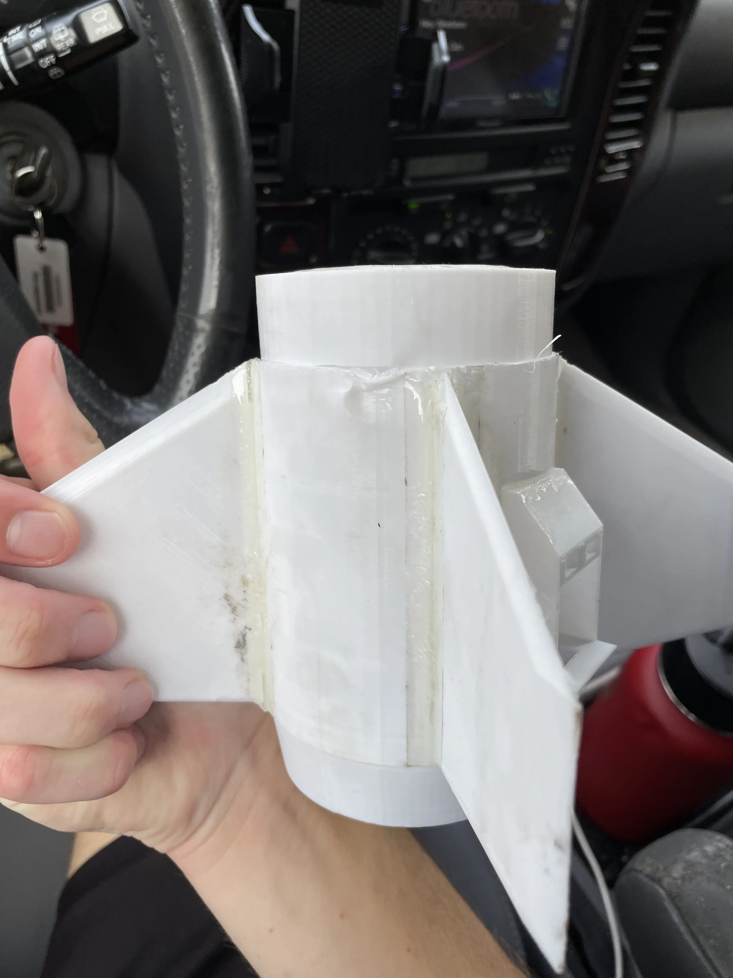
November 23, 2023: Mounting Motors
Over the past week, I have been designing perhaps one of my most complex components yet! I designed Harrier’s engine section with Fusion 360. The motor mount itself was not unusually complex, it is mainly a tube that adapts the engine, fins, cameras, and boattail to the body tube. The main addition to this engine section is that its motor tube is much wider since it needs to accommodate 38mm I motors rather than the 29mm G and H motors I have previously flown on. I also had to design an attachment point for the boattail.
The real challenge of this design came with the camera mounts. I had already decided that I wanted to add another mount for an outward-facing camera in addition to the downward-facing camera. This would not only provide another amazing view of the launch but would work to offset the drag from the original camera mount, keeping the rocket from veering to a harsher angle attack that would cause it to slow down. I worked to make the camera mounts as aerodynamic as possible, rounding out any corners and transitions. This took the most time as I had to be careful and use new tools, it helped me learn much more about Fusion 360! Once I finished the mount design, I cut away the camera hoods that keep the cameras from falling out. I added all of the latching pieces and began printing! The motor mount itself took a few tries to print, as I kept wanting to change small things and needed to do some printer maintenance, but I ended up with a well-finished part! I continued to iterate on the camera hoods until I got the best design that worked well with the system!

Designing the nosecone in Fusion360


Printed sections of the nosecone

Assembled nosecone and payload bay
November 22, 2023: Going With the Flow
Over the past couple of weeks, I have been hard at work continuing to model and design more complex parts on Fusion 360. Most recently, I have been designing and printing Harrier’s Nosecone! Using information learned from Richard Nakka’s Rocketry Website, I decided to make the nosecone fineness ratio or length-to-width ratio, 5:1. This means that since the rocket has a diameter of 79mm, the nosecone has a length of 395mm. I decided to go with these dimensions because they have practically all of the aerodynamic and stability benefits of a nosecone with a fineness ratio of 6:1 without the added weight. It also makes printing much easier, as my printer can only print in sections up to 140mm in height.
The tip of the nosecone needed to be rounded to avoid generating shockwaves in the air that would slow down the rocket. I rounded the tip with an arc that had the optimal radius of 15% of the radius of the nosecone, or 5.925mm.
The overall shape of the nosecone is meant to emulate the Von Karman nosecone design, which performs very well in a wide variety of subsonic, transonic, and supersonic speeds. Working with this in mind, I designed the profile of the nosecone to start tangent to the walls of the rocket before curving inward to a point before being rounded off at the tip.
To design this component, I drew the profile of the whole nosecone before revolving it around its center axis to create a 3d shape. The nosecone also has an insert, called a shoulder, that extends 40mm into the payload section of the rocket for connection purposes.
Finally, I divided the whole part into four sections with notches to line them up after I printed them. Once the parts were done printing, I glued them up with epoxy! While I was epoxying the nosecone, I also cut the payload bay tube down to size and epoxied it to its bulkhead.

From left to right: boattail, body tube coupler, Blue Tube
November 6th, 2023: Rocket R&D
This past month has been spent with lots of research and development work in the background! I have been hard at work figuring out how to build Harrier 1.
Since Harrier is meant to be somewhat of an aerodynamic pathfinder, I am trying to be as precise as possible in designing its parts to emulate the aerodynamics of a supersonic rocket. As part of this, I am using formulas from Richard Nakka’s Rocketry Website to design an aerodynamic nosecone for supersonic flight, which has a rounded tip and a 6:1 length-to-width ratio as well as an aerodynamic tail cone or “boattail” for the aft end of the rocket to improve airflow. I am also smoothing out surfaces on the fins, body tube, and motor mount in TinkerCAD and Fusion360.
Harrier is also being built with Blue Tubes as the airframe. Blue Tubes are basically mailing tubes on steroids: extremely tight woven tubes made of many layers of paper. These tubes are much stronger than the FedEx tubes I have been using and although they are heavier, are much better suited for this type of project. I have also modified the coupler between the main body tube and the payload section to be more inline rather than have a lip. This will provide a more secure joint and will improve aerodynamics by getting rid of unnecessary gaps. Harrier’s motor mount will also have an added camera mount opposite of the existing one. This will both balance out drag on the rocket to improve its angle of attack, as well as serve as a place to mount a camera pointed at the horizon out of the side of the rocket!

Early OpenRocket Simulation of Harrier 1 on an I218R motor
October 10, 2023: Next Steps
I am currently working on the next rocket, Harrier! Harrier will fly on 38mm I motors and will help me continue to push the limits and set new personal speed records. The development of Harrier will emphasize strength and aerodynamics. I will take care to use it to learn everything I can about flying at high speeds.
Hermes launching with Tiger 4 in the foreground


Hermes descending under its parachute
Shock diamonds!
September 23, 2023: Rolling With the Changes
We had three spectacular launches on Saturday! Despite not being able to go up to Kentucky to fly on high-power motors, we made do with G76G motors and got great data! Our new launch site at Chickasaw Trace Park in Columbia was optimal, as it is close, has a massive field, and we are free to do almost anything we want there. The bright-green-burning G76G motors also provided a good substitute for the H238T motor that we were planning to fly on, as it is just below the power that would be classified as a high-power motor. The G76G’s still got the rockets flying high and fast and provided a perfect environment to test out the Chute Release and onboard sensor unit! I am looking forward to applying what I learned from these launches and analyzing the data!
Quick burst dip before mixing
Quick burst dip after mixing
Coated igniters
September 18, 2023: A Chemistry Lesson
Today I did some chemistry! Since I will be using my own launch controller for this week’s launches, I will need some extra help with the igniters since it only runs on a 12v battery rather than the massive battery that we use at Bluegrass. To help the igniters get super hot even with lower voltage, I am using a compound made by a company called Quickburst. The Quickburst dip is a mix of Potassium Perchlorate (KClO4), a binding agent, and a coating agent. When the mix is ready to apply, you add Acetone, in this case, I used nail polish remover, which is 100% Acetone, and mix it until it becomes a liquid. Once the dip is a liquid, you dip the tips of the igniters into it to give them an extra kick! Potassium Perchlorate and Acetone are very flammable, so they make the igniters flare up with very little effort. You do have to be sure to keep this stuff away from flames though!
The payload bay camera

Hermes 2 and Tiger-4 during prelaunch testing
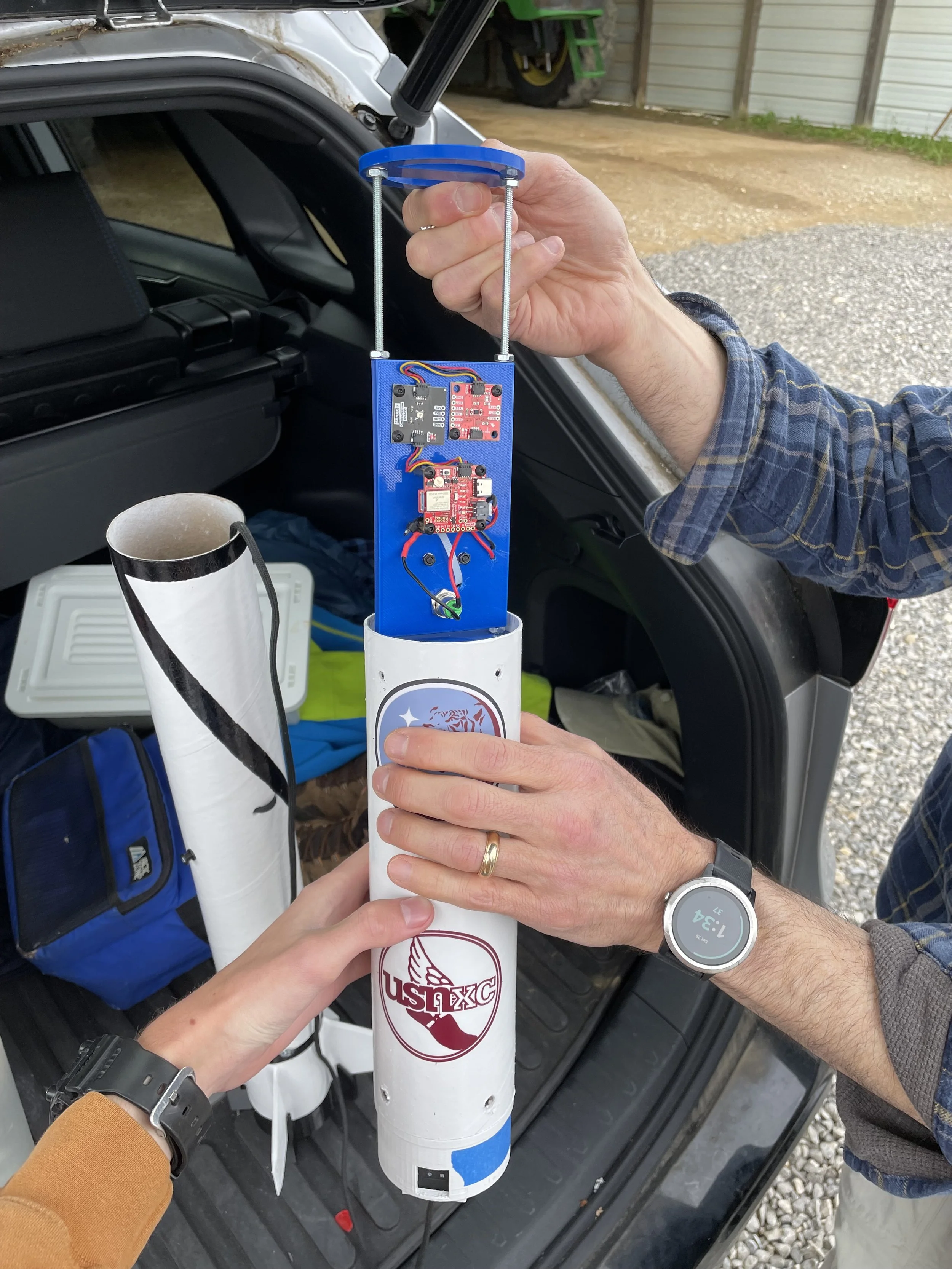
Electronics Bay #2

The interior view of Hermes 2 during testing
September 17, 2023: Dress Rehearsal
Today was a productive day of testing! I started off by charging up and testing the onboard cameras. The cameras worked well, but I had issues with one of the SD cards being glitchy that I’ll have to figure out. The main testing of the day involved setting up the new Chute Release and testing it with the parachute. I attached the parachute and parachute protector to the rocket in launch configuration and set up the Chute Release to wrap around them. I then put the Chute Release into test mode and had it release the parachute to simulate a flight.
Tiger-4 on the pad for testing

Jolly Logic Chute Release
September 15, 2023: Plan B
We are a little over the week out from the first set of launches for Project 767! The rockets are all ready for launch and I have been testing the new Chute Release that will keep the parachutes from causing the rockets to drift!
Unfortunately, it appears that there is no Bluegrass launch in Kentucky next Saturday as I originally planned. If we want to get any launches off next week, we will have to find a local field to launch at and stick to mid-power motors.
Luckily, we have found a nearby field at the Chickasaw Trace Park in Columbia and we have a backup plan! We will be launching Tiger-4 on three test flights on G76G motors to test out the electronics.

Tiger-4 (left) and Hermes 2 (right)
September 4, 2023: Launch Preparations
Today I worked on a few different things First, I measured and marked the spots for altimeter vent holes and rivet holes in the payload section of Tiger-4. The rivet holes are at the top of the payload section and allow the nosecone to be secured and removed easily. The vent holes are the larger four holes at the bottom of the payload bay and allow the air pressure inside the rocket to change so that the altimeter can measure the altitude of the rocket in the air.
After I drilled the holes, I epoxied the payload section to its bulkhead that attaches it to the rest of the rocket and then epoxied the nosecone together. Once the epoxy dried, I painted both parts with a fresh coat of white gloss paint.
In order to get both rockets ready to launch, I attached the shock cords to both rockets. The shock cord is a length of paracord about twice the length of the rocket that keeps both halves together after the parachute deploys. The shock cord is also what keeps the parachute attached to the rocket. It needs to be strong and mounted well so that it absorbs the shock of parachute deployment.

August 9, 2023: Heavy Lifting
Today, I certified my 38mm engine mount design by testing it with weights! I turned an adapter that resembles a barbell out of white pine wood using a lathe. The adapter allowed me to use free weights with an inner diameter of 50.8mm in a 38mm motor tube! The entire structure held 345 lbs of weight before I had to stop the test because of the stand breaking. The only damage to the engine mount itself was some minor buckling at the forward end!
April 29, 2023: Rocket Farm
Today I launched the first flight of Hermes! It flew on an H220T motor and carried the first sensor payload! Hermes likely hit a top speed of around Mach 0.5 or around 562 ft/s, but the flight was cut short because of an early parachute deployment just after motor burnout. Hermes appeared to mostly stay together during free fall and landed separately from its parachute. Unfortunately, we were unable to find it because it landed in a muddy field growing a dense crop of wheat. Future flights will include GPS in the payload! After retracing my steps and going over what video I have of the flight, I am pretty sure that the early parachute deployment was caused by a damaged ejection delay charge that burned through to early after motor burnout. I am pretty sure that it was damaged when I had to remove it from the motor’s forward closure after I had installed it incorrectly. I will be sure to take extra care with future flights to properly install these components the first time!